
基本制图标准 SECTION O TWO G DRAWING STANDARD
图样是工程界的技术语言。作为技术的共同语言,必须有统一的规范,这些规范就是制图标准。本书采用了国家标准《技术制图》和行业标准《水利水电工程制图标准》。技术制图标准与行业标准不同时,应遵循技术制图标准。本节主要介绍:图纸幅面和格式、比例、图线、字体、剖面符号和尺寸注法六项基本制图标准,其它有关标准将在后续章节中分别介绍。
Engineering drawings are the technical language in engineering field. As a common language of technology, must have a unified standard, the specification is drawing standards. This book uses the national standard “TECHNICAL DRAWINGS STANDARD” and the industry standard “WATER CONSERVANCY AND HYDROPOWER ENGINEERING DRAWING STANDARDS”. When Technical drawing standards don’t agree with industry standards, drawings should follow the technical drawing standard. This section mainly introduces: drawings format and format, proportion, graphs, font, section symbols and dimension, other standards will be introduced in the following chapter.
图纸幅面和格式 G DRAWING T SHEET D AND LAYOUT
各类技术图样都应采用国标《技术制图 图纸幅面和格式》(GB/T 14689-93)规定的图纸幅面和格式。
All kinds of technical drawings should be with the national standard “ TECHNICAL DRAWINGS DRAWING SHEETAND FORMAT” (GB/T 14689-93) set of drawings sheet and format.
1.图纸幅面 DRAWING SHEET
图纸幅面即图纸的面积,图纸的短边×长边用 B×L 表示。制图标准规定了五种不同尺寸的基本图幅见表 1-2。绘制技术图样时,应优先选用基本幅面。
There are five kinds of standard sheets and are shown in table 1-1.in fact, drawing sheet is the area of paper sheet. It can show A=B×L. One should firstly choose standard drawing sheet to express engineering solids.

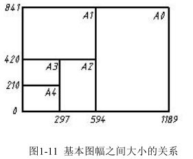
由表 1-2 可以看出,图纸幅面以 A0、A1、A2、A3、A4 为代号,基本图幅之间大小的关系如图 1-11 所示。
Table 1-2 shows the size of every standard drawing sheet. The relation of different sheet is shown in fig1-11.
图幅在应用中面积如果不够大,允许加大图幅面积,具体尺寸必须参照执行有关的制图标准。
If the sheet is not big enough, allow large area, the specific size should refer to the implementation of the relevant drawing standards.
图框格式 E FRAME FORMAT
绘制图样时,必须在图纸上用粗实线画出图框,图形只能绘制在图框内。图框格式分为不留装订边和留有装订边两种,但同一产品的图样只能采用一种格式。
One need to draw border with thick line and the drawings cannot allow going beyond the frame. There are two formats. Frame format is divided into without binding edge and a binding edge, while the drawings of the same product can only use a format.
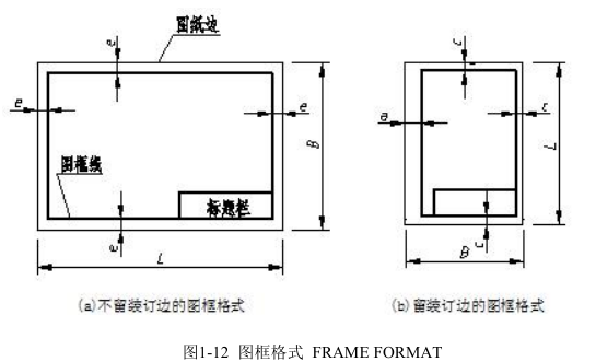
不留装订边图纸的图框格式如图 1-12(a)所示,周边的尺寸见表 1-2。国际上早已采用自动晒图机晒图,它可以完成复制、剪切、折叠等全过程,若需要附加装订边,可以粘贴一条具有装订孔的装订胶带。这种不留装订边的图纸对绘图、复制、折叠、装订和使用都十分方便,应优先选用。留有装订边图纸的图框格式如图 1-12(b)所示。
Without binding edge drawing is format as shown in Figure 1-12 (a) and its neighborhood sizes as shown in table 1-2. The international Blueprint Apparatus has already realized copying, trimming, folding and so on. If the need for additional binding edge, can be pasted with a binding hole tape. This does not leave the binding edge on drawing; copying, folding, binding and convenient use should be preferred. Binding edge drawing frame format is shown in Figure 1-12 (b).
标题栏 TITLE BLOCK
无论采用哪一种图框格式, A4 图纸都应竖放,其他代号的图纸横放,都还必须在图框右下角画出标题栏。标题栏(简称图标)是图样的重要内容之一,图标的外框线用粗实线绘制,分格线用细实线绘制,图标的右边框和下边框线应与图框线重合。
No matter which kind of frame format, A4 drawings should be upright, other drawing sheets layout in horizontally. Title block must draw in the lower right corner of draw frame. The title bar (referred to as the icon) is one of the important contents of drawings, icon border line drawn with thick lines, dividing line drawn with thin line, right frame icon and border lines should coincide with the frame line.
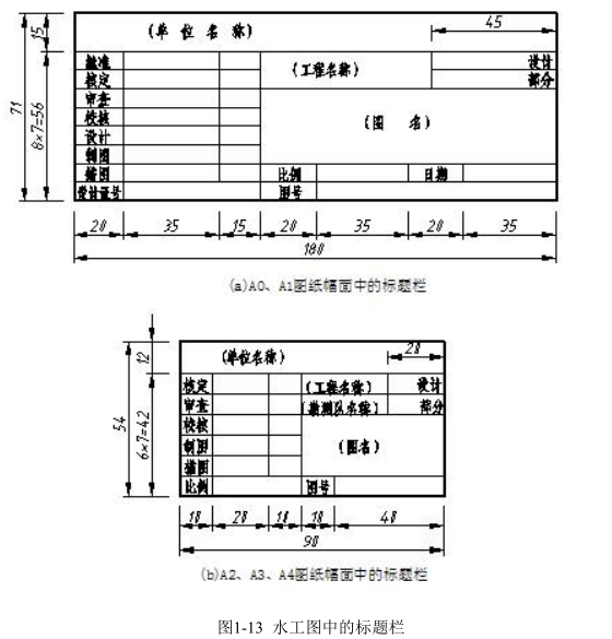
图 1-13 所示,是《水利水电工程制图标准》中推荐的水工图样标题栏的格式和尺寸。
Hydraulic drawing title blocks recommended by “ WATER CONSERVANCY AND HYDROPOWER ENGINEERING DRAWING STANDARDS” are shown in fig 1-13.
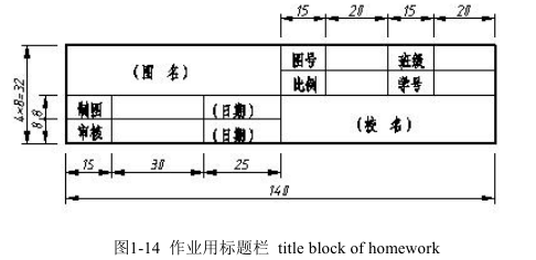
本课程作业中建议采用图 1-14 所示的标题栏。
比例 SCALE
图样中图形与其实物相应要素的线性尺寸之比称为比例。国标《技术制图比例》(GB/T 14690-93)对图样中的比例大小和注写方式都作了规定。绘制图样时,应根据物体的大小及其形状的复杂程度,由表 1-3 规定的系列中选取适当的比例。比例= 图形:实物。
Scale: dimension of drawing: size of actual object Drawings contain a scale that helps readers understand the proportions of the map. A verbal scale is simply a statement on a map that indicates the map's proportion. For example, a verbal scale might read “one mm equals one meter”.
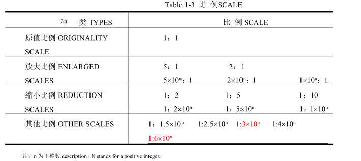
无论采用何种比例,图中所注尺寸均应是物体的真实尺寸,与比例无关。
Notice: all dimensions are the real sizes of object and have nothing to do with the scales.
在图纸上必须注明比例,当整张图纸只用一种比例时,应统一注写在图标中的比例栏内。否则,应在各视图中分别注写。
The scale must be shown in the drawing. If the drawings have the same scale, should be written in the title block. Otherwise, should write notes respectively in each view.
图线 LINE STYLES
在绘制图样时,应遵循国标《技术制图 图线》(GB/T 17450-98)对图线的规定。
Engineering drawings should follow the national standard “ technical drawing graph ” (GB/T 17450-98) Regulations on lines in China.
1.图线的形式和用途 line styles and their utilization
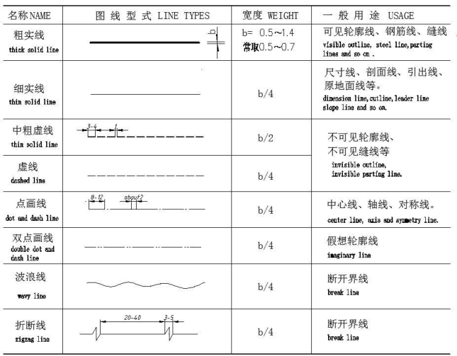
图线是组成图形的基本要素。为了使图样中表达的内容主次分明,图线有粗线、中粗线和细线之分,三者的的宽度比率为 4:2:1。所有线型的图线宽度应按图样的类型和尺寸大小在下列数系中选择:0.13、 0.18 0.25、 0.35、 0.5、 0.7、 1、 1.4、2.0mm。技术制图标准中用 d 表示所有线型的图线宽度。粗实线的图线宽度习惯上用字母 b 表示,并根据图样的比例和复杂程度一般在 0.5~1.4mm 之间选用,常用的 b 值为 0.5~0.7mm。
Line is the basic elements of graphics. In order to make drawing clear, one can select different widths of lines to show. The ratio of the width of the 4:2:1. All linear line width should be chosen from the following number system: 0.13, 0.18 0.25, 0.35, 0.5, 0.7, 1, 1.4, 2.0mm. Technical drawing standard chooses d to stand for width of all lines. The width of thick line often is shown by letter b. The range of value of d is around 0.5~1.4mm generally. The commonly used b value of d is about 0.5 ~0.7mm.
水工图常用的线型形式和用途见表 1-4。

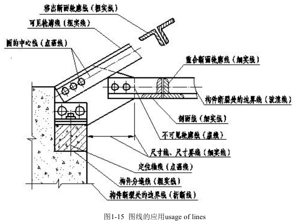
各种图线的应用举例如图 1-15 所示。 Application of lines is shown in fig 1-15.
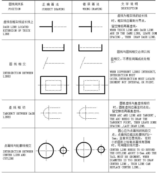
2.图线画法的规定 regulations of lines
同一张图纸上同类图线的宽度应基本一致;虚线、点画线的线段长度和间隔应大致相等。图线的宽度靠削磨铅笔芯来控制,线段的长短和间隔靠目测控制,图线的浓淡靠手画图时的力度控制。图线的规定画法见表 1-5。
The width of the same drawing should be consistent. For example, the length of segment of dash line, center line should be approximately equal. So do the intervals. Sharpening cone can control the width of line; however, segment and interval can do through visual inspection. Drawing strength determines the light or dark of lines Graph representations are shown in table 1-5.
字体 FONT
图样中的文字应按国标《技术制图 字体》(GB/T 14691-93)的规定书写。字体是图样中重要的组成部分,书写字体必须做到:字体工整、笔划清楚、间隔均匀、排列整齐。
The texts of drawing should be written based on national standard “ TECHNICAL DRAWING STANDARD FONT ” (GB/T 14691-93). The font is an important part of drawing, writing font: font must be neat, clear and so on.
字体的号数即字体的高度 h,分为八种:20、14、10、7、5、3.5、2.5、1.8mm。如果需要写更大的字,其字体高度应按的比率递增。
1.汉字 CHINESE CHARACTER
汉字应写成长仿宋体字,并应采用国家正式公布的简化字。汉字字高不应小于3.5mm,字宽一般为 h/ 。长仿宋体字的示例如图 1-16 所示。
Chinese characters should be written in Fangsong, and should use the simplified character officially announced by China. The height of Chinese characters character should not be less than 3.5mm. The width is h/ . Long Fangsong example as shown in figure 1-16.
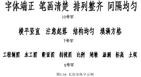
长仿宋体字的书写要领是:横平竖直、起落有锋、结构匀称、填满方格。建议初学者打格书写,以保证字体大小一致、排列整齐。长仿宋体的基本笔画和书写方法见表 1-6。
Key points of writing long Fangsong is: horizontal and vertical landing, with front, structural symmetry, filled squares. It is recommended for beginners to play writing, in order to ensure uniform, neatly arranged in the font size. The basic strokes and the writing method of long Fangsong are shown in table 1-6.
书写时应特别注意起笔、运笔、收笔、转折,必须做到运笔流畅、笔锋突出。练字不能急于求成,要分三步进行:第一步先练基本笔画,第二步练偏旁部首,第三步练整字。只有多看多写持之以恒,才能水到渠成。
Writing should pay special attention to the usage of pencil. First stroke, last stroke, wielding pencil and turning must accomplish smoothly. Calligraphy cannot be anxious for success. It can be divided into three steps: the first step is to practice basic strokes; second step is to train structure of Chinese characters. The third step is to write whole character.in a word, Practice makes perfect.
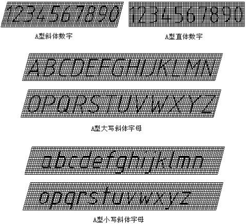
2.数字和字母 NUMBER AND LETTER
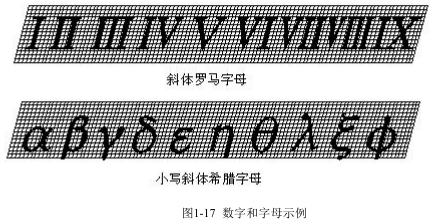
数字应写成阿拉伯数字,字母应写成拉丁字母和罗马、希腊字母。数字和字母都分 A 型和 B 型。A 型字体的笔画宽度为字高的 1/14,B 型字体的笔画宽度为字高的1/10。在同一图样上,只允许选用一种形式的字体。为了与汉字协调,建议数字和字母采用 A 型字体。
Figures should be written in Arabia digital. The letter should be written in the Latin alphabet , Rome, and the Greek alphabet. Numbers and letters are divided into A type and B type. Stroke width A fonts for words is 1/14 of height. stroke width B fonts for words is 1/10 height. In the same drawing, only font is permitted. In order to coordinate with Chinese characters, suggested by A type font numbers and letters.
数字和字母可以写成斜体或直体。斜体字字头向右倾斜,与水平基准线成 75°。图样中常采用斜体字,如图 1-17 所示。
Numbers and letters can be written in italics or straight. Italics head tilted to the right, at an angle of 75 degrees with the horizontal reference line. Italics often use pattern, as shown in figure 1-17.
剖面符号 SECTION SYMBOL
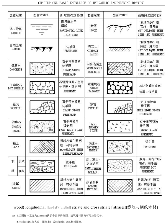
工程中使用的建筑材料类别很多。画剖视图与断面图时,必须根据建筑物所用的材料画出建筑材料图例(技术制图中统称为剖面符号),以区别材料类别方便施工。
Many building materials are often used in engineering. One should draw section symbols during expressing section views and cut section views to distinguish the categories of construction materials.
图样中的剖面符号应按国标《技术制图》和行业标准《水利水电工程制图标准》的规定绘制。水工图中常用的剖面符号见表 1-7。
Section symbols should be drawn in accordance with the provisions of the national standard “ TECHNICAL DRAWINGS STANDARD ” and the industry standard “ WATER RESOURCES AND HYDROPOWER ENGINEERING DRAWING STANDARDS ” .Section symbols in common use are shown in table 1-7.

尺寸注法 DIMENSIONING
国标《技术制图》(GB/T 16675.2-1996)中仅对尺寸标注的简化表示作了规定,尺寸标注的基本规则和注法应遵循行业标准《水利水电工程制图标准》。本节只介绍尺寸标注的一般规则,专业工程图样的尺寸标注,将在以后有关章节中分别介绍。图形只表示物体的结构形状,物体的真实大小应以图中标注的尺寸数值为依据。
1.尺寸的组成 FACTORS OF DIMENSION
一个完整的尺寸由尺寸界线、尺寸线、尺寸起止符号、尺寸数字四部分组成,如图 1-18 所示。
A complete dimension consists of extension line, dimension lines, arrowheads, and figures.
They are shown in fig 1-18.
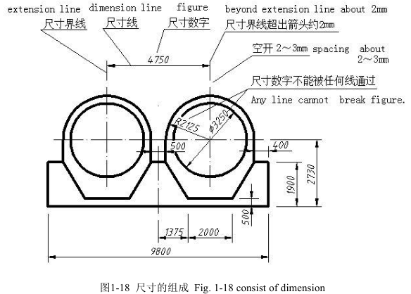
(1)尺寸界线。尺寸界线表示所注尺寸的范围,用细实线绘制。尺寸界线可从图形的轮廓线、轴线或中心线处引出,也可以直接利用轮廓线、轴线或中心线作尺寸界线。绘制尺寸界线时,引出端与轮廓线之间一般留有 2~3mm 间隙,另一端应超出尺寸线约 2mm。
Extension lines: extension lines are thin solid lines and extend from the object to show the limits of a dimension. The extension lines should not touch the outline of the drawing feature and a small gap should be left about 2–3 mm. The extension lines should continue for the same distance about 2–3 mm past the dimension line.
(2)尺寸线。尺寸线表示尺寸的方向,用细实线绘制。尺寸线应与被注的线段等长且平行,距离所注的线段一般在 7mm 以上。尺寸线不能用其它任何图线代替,必须单独画出。
Dimension lines are thin solid lines and parallel to the line segment being dimensioned. The space between dimension lines or between a dimension lines and the closest outline should be 7 to 10mm. Dimension lines must be drawn and cannot be replaced by other lines.
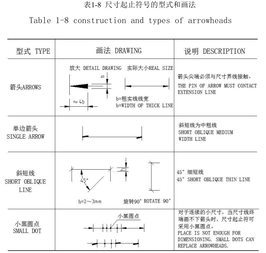
(3)尺寸起止符号。尺寸起止符号表示尺寸的起止点。尺寸起止符号的形式和有关规定见表 1-8。在圆上标注半径、直径与标注角度、弧长的尺寸起止符号一律采用箭头,同一张图样中线性尺寸的起止符号只能在箭头和斜短线之间选用一种形式。
Arrowheads: arrowheads are placed at the ends of dimension lines and they must touch the corresponding outlines. Arrowheads should be approximately triangular, must be of uniform size and shape and in every case touch the dimension line to which they refer. Arrowheads drawn manually should be filled in.
(4)尺寸数字。尺寸数字表示物体的真实大小。尺寸数字一般用 3.5 号斜体阿拉伯数字书写,同一张图样中尺寸数字的大小应一致。尺寸数字不可被任何图线或符号通过,当无法避免时,必须将图线或符号断开,如图 1-18 所示。同一方向的若干尺寸,应尽量注写在一条线的位置上,当不能在一条直线上注写时,应小尺寸注内层,大尺寸注外层,避免尺寸线交叉。互相平行的尺寸线间的间距一般在 7mm 左右。
Figures:Dimension numerals are placed above the dimension line, and should keep some gap from the dimension line. To enable dimensions to be read clearly, figures are placed so that they can be read from the bottom of the drawing, or by turning the drawing in a clockwise direction, so that they can be read from the right-hand side. One should know numerals should not be broken by any lines. Basic rules for dimensioning:
1. Dimension line cannot replace by other line and must draw.
2. Figures of dimension show the real size of solid.
3. Dimensions in drawings are given in millimeters without explanation.
4. The unit is meter in general layout drawing or level.
2.尺寸的单位 UNIT of DIMENSION
行业标准《水利水电工程制图标准》中规定:标高、桩号及规划图、总布置图的尺寸以米为单位,其余尺寸以毫米为单位时,图中不必说明,否则应说明尺寸单位。
3.尺寸的一般注法 Methods of dimensioning
水工图中尺寸一般注法的规定,见表 1-9。
Linear dimension( 线性尺寸标注)
For small size, when dimensioning position cannot place figures or arrowheads, the number can note the lateral of dimension line or use small black spots instead of arrowheads.
Dimensioning circles( 圆尺寸标注)
The symbol preceding the figure is used for specifying diameters and it should be written as large as the figures.
Dimensioning arcs( 圆弧尺寸标注)
The letter R preceding the figure is used for specifying radii and it should be written as large as the figures. Note that the dimension line is drawn through the arc center and the arrowhead touches the arc.
Angular dimensions( 角度标注)
Angular dimensions on engineering drawings are expressed as follows: The figure of angle should be written in horizontal direction.
Dimensioning elevation( 高程标注)
The symbol preceding 的 前面的 [priˈsi:diŋ] the figure is used for specifying elevation. There are two different symbols to express the elevation of plan drawing and elevation drawing. The dimensions are quoted [kwəutid] in meters and the figures should keep three digits of the decimal point.
Dimensioning slope( 坡度标注)
The arrow indicates the direction of slope and uses the rate to dimension the size of slope.

