水利工程制图

武心嘉、汪艳芳

目录

  • 1 制图基本知识 Basic Knowledge of Drawing
    • 1.1 绪论 Introduction
    • 1.2 制图工具及其用法 Drawing Tools and Their Utilization
    • 1.3 国家标准有关规定 Related Provisions in National Standards
    • 1.4 几何作图geometric construction
    • 1.5 平面图形的绘制 The drawing of plane graphics
  • 2 投影的基础知识 The basics of projection
    • 2.1 投影法和投影特性 Projection method and projection properties
    • 2.2 工程中常用的四种投影图Four kinds of projection drawings commonly used in engineering
    • 2.3 物体的三面投影图 Three-sided projection of an object
  • 3 点线面的正投影 Projection of point、line and plane
    • 3.1 点的投影 Projection of Point
    • 3.2 直线的投影 Projection of Line
    • 3.3 平面的投影 Projection of Plane
    • 3.4 直线与平面、平面与平面的相对位置The position of a line relative to a plane, plane relative to a plane
  • 4 立体 Stereoscopic
    • 4.1 平面体的投影Projection ofProjection of  Planar Solids
    • 4.2 平面立体表面上的点和线 Points and lines on a planar solid surface
    • 4.3 平面立体截交线Plane stereo intersection line
    • 4.4 曲面立体的投影Stereoscopic projection of a curved surface
    • 4.5 曲面立体表面上的点和线Points and lines on the surface of a curved surface
    • 4.6 曲面立体的截交线Curved solid intersection
  • 5 立体表面相交Intersections of solids
    • 5.1 概述Overview
    • 5.2 两平面立体相交Two plane solids intersect
    • 5.3 平面体与曲面体相贯Intersections Between Planar and Curved Solids
    • 5.4 两曲面体的相贯线 The intersecting line of two curved bodies
    • 5.5 常见两曲面立体相贯线的讨论Discussion on the intersecting line of two surfaces
  • 6 组合体 composite solid
    • 6.1 组合体构成分析 Composition analysis
    • 6.2 组合体视图的画法 Composition View
    • 6.3 组合体的尺寸标注 The dimension of the assembly
    • 6.4 组合体视图的阅读 Reading the composite view
  • 7 轴测图的画法  construction of axonometric drawing
    • 7.1 轴测图的基本知识 Basic Knowledge
    • 7.2 平面体的正等测 Isometric Drawing
    • 7.3 平面体的斜二测 Cabinet Drawing
    • 7.4 曲面体的正等测 Isometric Drawing of Curved Solids
    • 7.5 曲面体的斜二测 Cabinet Drawing of Curved Solids
  • 8 工程形体的表达方法Expression methods of engineering objects
    • 8.1 视图 Views
    • 8.2 剖视图 Section View
    • 8.3 断面图 Cross Section
    • 8.4 简化画法和规定画法Simplified and prescriptive drawing
    • 8.5 视图的综合运用 Comprehensive use of views
    • 8.6 补充
  • 9 水工建筑物中常见的曲面 Curved surfaces in water conservancy project
    • 9.1 概述
    • 9.2 椭圆柱和椭圆锥
    • 9.3 双曲抛物面
    • 9.4 组合面Combination of surface
  • 10 标高投影 Projection with heights
    • 10.1 点、直线、平面 Points, lines, planes
    • 10.2 两平面的交线
    • 10.3 曲面和地形面 Curved and topographic surfaces
    • 10.4 标高投影在工程中的应用Application in engineering
  • 11 水利工程图 Hydraulic drawing
    • 11.1 水工建筑物和水工图 Hydraulic structures and drawings
    • 11.2 水利工程图表达 Expression of Hydraulic Engineering Drawing
    • 11.3 水工图的尺寸标注 Dimensioning of hydraulic drawings
    • 11.4 水工图的绘制 Drawing of hydraulic drawings
    • 11.5 水工图的阅读 Reading of hydraulic drawings
  • 12 建筑施工图Building construction drawing
    • 12.1 概述Overview
    • 12.2 建筑总平面图General plan of the building
    • 12.3 建筑平面图Construction plan
    • 12.4 建筑立面图 Elevation of Building
    • 12.5 建筑剖面图Building profile
    • 12.6 建筑详图 Architectural detailed drawing
平面体的投影Projection ofProjection of  Planar Solids

平面体的投影Projection of  Planar Solids

       识读平面体三视图,就是依据平面体三视图的图形特征想象出它的立体形状的过程。由上述可知,平面体三视图中,两个视图外轮廓是矩形,所表示的形体一定是柱体,对应的多边形是什么形状就是什么棱柱;两个视图外轮廓是三角形,所表示的形体一定是锥体,对应的多边形是几边形就是几棱锥;两个视图外轮廓是梯形,所表示的形体一定是台体,对应的多边形是几边形就是几棱台。无论是完整的还是部分的平面体的三视都具有此图形特征。

       Reading three views of basic solids is to imagine the solid in space based on its three views. As we know, if its two views are both rectangles, the solid must be a prism. The name depends on the polygon. If two views are both triangles, solid must be a pyramid. If the two views are both trapeziums[trә'pi:ziәm],  the views show frustum of a pyramid. Whenever the planar solid is complete or part , it should follow the feature characteristics.

【例 4-1】逐一分析图 4-1 所示平面体的三视图,想象出它们的立体形状。 Please produce the solid based on three views of planar solid.

分析 analyze

      图 4-1(a)所示三视图,左视图和俯视图两个视图为矩形,一定是柱体,特征图主视图为“凸”字形(底面实形),可知该形体是前后底面为凸字形的“凸形柱”,立体形状如图 4-2 (a)所示。

      According to the given three views, left and top views are both rectangles, one can make sure it is a prism. The feature view is the front view and the shape is 凸( show the true shape of front and back faces), the solid as shown in fig 4-2.

      图 4-1 (b)所示三视图,主视图和俯视图两个视图都是三角形,一定是锥体,特征图左视图为四边形,可知该形体是锥尖向左,底面平行于 W 投影面的四棱锥,立体形状如图 4-2 (b)所示。

      Figure 4-1 (b) shows that the left and top views both triangles, it indicates that the solid is a cone. The feature view is a quadrangle; the solid is a cone tip to the left, bottom surface is parallel to the W projection plane, three-dimensional shape as shown in Figure 4-2 (b).

      图 4-1 (c)所示三视图,有两个视图为梯形,一定是台体,特征图是 1/2 四棱台底面形状。可知该形体为左半四棱台,立体形状如图 4-2 (c)所示。

      Figure 4-1 (c) shows that there are two views are both trapezoids[ˈtræpəzɔɪd], must be a frustum of a pyramid, feature view is 1/2 frustum of a rectangular pyramid. The solid is the left semi frustum of a rectangular pyramid. Three-dimensional shape is shown in Figure 4-2(c).

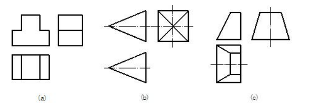
                          图4-1 平面体三视图的识读举例  Fig 4-1 samples of reading planar solids

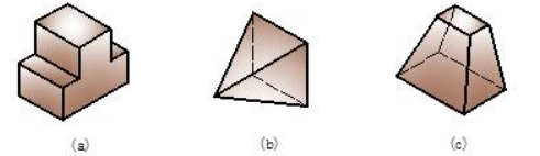
                              图4-2 平面体三视图识读示例对应的立体形状  Fig 4-2 solids in space

2.曲面体三视图的识读 reading of curved solids

曲面体三视图的读图依据是曲面体三视图的图形特征。无论是完整还是部分曲面体

的三视图都具有上述的图形特征。

The rule of reading curved solids is the projection feature of curved solids. Whenever the

solid is complete or partial [ˈpɑ:ʃəl].

【例 4-2】识读图 4-3 所示曲面体的三视图。Please imagine the solids based on given views.

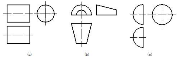
                        图4-3 曲面体三视图的识读举例  Fig 4-3 samples of reading curved solids

分析 analyze

       图 4-3(a)所示三视图,主视图和俯视图两个视图为矩形,是柱体,特征图左视图是圆,可知该形体是轴线垂直 W 投影面的圆柱。

       Figure 4-3 (a) shows that the front and top views are both rectangles and the solid must be a column. The feature view is a circle. So the solid is a cylinder and its axis is perpendicular to the W – projection plane. 

       图 4-3(b)所示三视图,俯视图和左视图都是梯形,主视图是特征图为上半圆,可知该形体是轴线垂直 V 投影面的上半圆台。

       Figure 4-3 (b) shows the front and left views are both trapezoids, and its feature view is a semi- circle, so the solid is a frustum of cone and its axis is perpendicular to the V–projection plane.

       图 4-3(c)所示三视图是直径相等的三个圆形线框,但主视图、俯视图为半圆,是左半部,可知该形体是左半圆球。

       Figure 4-3 (c) shows the front and top views are both half circles and the left view is a circle,so the solid is a semi-sphere.

       基本体三视图的图形特征是今后画图和读图的依据之一,必须熟记。

       Feature characteristics of basic solids are not only the fundamental of drawing but also the basis of reading. One needs to keep them in mind during learning engineering drawing.