水利工程制图

武心嘉、汪艳芳

目录

  • 1 制图基本知识 Basic Knowledge of Drawing
    • 1.1 绪论 Introduction
    • 1.2 制图工具及其用法 Drawing Tools and Their Utilization
    • 1.3 国家标准有关规定 Related Provisions in National Standards
    • 1.4 几何作图geometric construction
    • 1.5 平面图形的绘制 The drawing of plane graphics
  • 2 投影的基础知识 The basics of projection
    • 2.1 投影法和投影特性 Projection method and projection properties
    • 2.2 工程中常用的四种投影图Four kinds of projection drawings commonly used in engineering
    • 2.3 物体的三面投影图 Three-sided projection of an object
  • 3 点线面的正投影 Projection of point、line and plane
    • 3.1 点的投影 Projection of Point
    • 3.2 直线的投影 Projection of Line
    • 3.3 平面的投影 Projection of Plane
    • 3.4 直线与平面、平面与平面的相对位置The position of a line relative to a plane, plane relative to a plane
  • 4 立体 Stereoscopic
    • 4.1 平面体的投影Projection ofProjection of  Planar Solids
    • 4.2 平面立体表面上的点和线 Points and lines on a planar solid surface
    • 4.3 平面立体截交线Plane stereo intersection line
    • 4.4 曲面立体的投影Stereoscopic projection of a curved surface
    • 4.5 曲面立体表面上的点和线Points and lines on the surface of a curved surface
    • 4.6 曲面立体的截交线Curved solid intersection
  • 5 立体表面相交Intersections of solids
    • 5.1 概述Overview
    • 5.2 两平面立体相交Two plane solids intersect
    • 5.3 平面体与曲面体相贯Intersections Between Planar and Curved Solids
    • 5.4 两曲面体的相贯线 The intersecting line of two curved bodies
    • 5.5 常见两曲面立体相贯线的讨论Discussion on the intersecting line of two surfaces
  • 6 组合体 composite solid
    • 6.1 组合体构成分析 Composition analysis
    • 6.2 组合体视图的画法 Composition View
    • 6.3 组合体的尺寸标注 The dimension of the assembly
    • 6.4 组合体视图的阅读 Reading the composite view
  • 7 轴测图的画法  construction of axonometric drawing
    • 7.1 轴测图的基本知识 Basic Knowledge
    • 7.2 平面体的正等测 Isometric Drawing
    • 7.3 平面体的斜二测 Cabinet Drawing
    • 7.4 曲面体的正等测 Isometric Drawing of Curved Solids
    • 7.5 曲面体的斜二测 Cabinet Drawing of Curved Solids
  • 8 工程形体的表达方法Expression methods of engineering objects
    • 8.1 视图 Views
    • 8.2 剖视图 Section View
    • 8.3 断面图 Cross Section
    • 8.4 简化画法和规定画法Simplified and prescriptive drawing
    • 8.5 视图的综合运用 Comprehensive use of views
    • 8.6 补充
  • 9 水工建筑物中常见的曲面 Curved surfaces in water conservancy project
    • 9.1 概述
    • 9.2 椭圆柱和椭圆锥
    • 9.3 双曲抛物面
    • 9.4 组合面Combination of surface
  • 10 标高投影 Projection with heights
    • 10.1 点、直线、平面 Points, lines, planes
    • 10.2 两平面的交线
    • 10.3 曲面和地形面 Curved and topographic surfaces
    • 10.4 标高投影在工程中的应用Application in engineering
  • 11 水利工程图 Hydraulic drawing
    • 11.1 水工建筑物和水工图 Hydraulic structures and drawings
    • 11.2 水利工程图表达 Expression of Hydraulic Engineering Drawing
    • 11.3 水工图的尺寸标注 Dimensioning of hydraulic drawings
    • 11.4 水工图的绘制 Drawing of hydraulic drawings
    • 11.5 水工图的阅读 Reading of hydraulic drawings
  • 12 建筑施工图Building construction drawing
    • 12.1 概述Overview
    • 12.2 建筑总平面图General plan of the building
    • 12.3 建筑平面图Construction plan
    • 12.4 建筑立面图 Elevation of Building
    • 12.5 建筑剖面图Building profile
    • 12.6 建筑详图 Architectural detailed drawing
平面体的正等测 Isometric Drawing

第二节 平面体轴测图的画法 SECTION  TWO  AXONOMETRIC  DRAWING  OF  PLANNAR  SOLIDS

一、平面体正等测的画法 isometric drawing of planner solids

       如图 7-2(a)所示,正等测的轴间角∠XOY=∠YOZ=∠ZOX=120°。OZ 轴成垂直位置,OX 轴和 OY 轴可用 30°三角板配合丁字尺绘出。轴间角的大小说明轴测图中长、宽、高方向的画法。

       The isometric angles among axis are ∠XOY=∠YOZ=∠ZOX=120°and the OZ axis is in the vertical position, the OX and OY axis can be drawn with 30 °squares. As shown in Figure 3-2 (a)

        正等测的轴向伸缩系数 p=q=r=0.82,为了画图简便,常采用简化轴向伸缩系数p=q=r=1作图,因而正等测图比实际物体的轴测图放大了1/0.82倍,即1.22倍,如图7-2(b)所示。轴向伸缩系数说明了量取长、宽、高尺寸时所采用的比例。

        The isometric  deformation coefficients are p=q=r=0.82. The coefficient is often simplified with 1 in order to make it easy for construction. That is to say the isometric drawing is larger than the true object.as shown in 7-2(b).

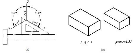
                         图7-2 正等测的轴间角和轴向伸缩系数 parameters of isometric projection

       画轴测图常用的方法有:特征面法、叠加法、切割法。画轴测图时,轴测图上不必画出轴测轴,可画出参照轴测轴,然后以测量尺寸方便为原则选定起画点,依据“平行性”、“可量性”画出。

       Now we introduce several commonly used methods in drawing axonometric projection. Such as feature surface, superposition, and cutting methods. One doesn’t need to draw axonometric axis ,however, One can draft reference axis to make it convenient and must follow the construction principles during making axonometric drawings.

1.特征面法 feature surface

       特征面法用于画基本体轴测图。特征面法画轴测图的思路是:对柱类形体,先画出反映柱体形状特征的可见底面,再画出可见的侧棱,然后画出另一底面的可见轮廓线,如图 7-3 所示;对台(或锥)类形体,先画出两底面(或底面和锥尖),再画出可见的侧棱,如图 7-4 所示。

       Characteristic surface method is useful for drawing axonometric projection of basic solids. Then we follows these steps. Firstly, finish axonometric drawing of the visible feature base of object. Then draw visible side edges, finally produce the projection of the other base. As shown in fig7-3 and fig 7-4.

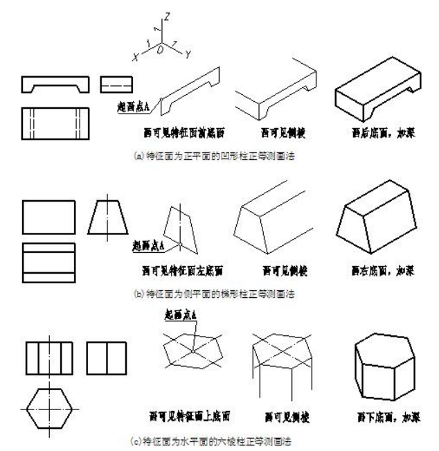
                                 图7-3 用特征面法画柱类形体正等测的示例samples of feature base

2.叠加法 superposition method

       叠加法用于画叠加体轴测图。叠加法画轴测图的思路是:从主到次逐个画出各基本体的轴测图,擦去被遮挡的图线。叠加时一定要注意基本体之间的定位。

       Superposition method does work in making superposition type solids. The idea is to construct axonometric drawing of every basic solid from primary to secondary solids and ignore invisible outlines. Please pay attention to the relative position among basic solids.

       图 7-5 所示是用叠加法画挡土墙正等测的作图步骤。挡土墙可看成由一个直十棱柱和两个三棱柱组合而成。应先画主体直十棱柱,再按三棱柱的位置逐一将两个三棱柱画出,完成作图。

       The retaining wall can be regarded as three prisms. The construction steps are as follows.

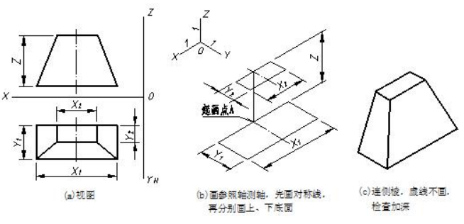
                              图7-4 用特征面法画台类形体正等测的示例sample of feature base

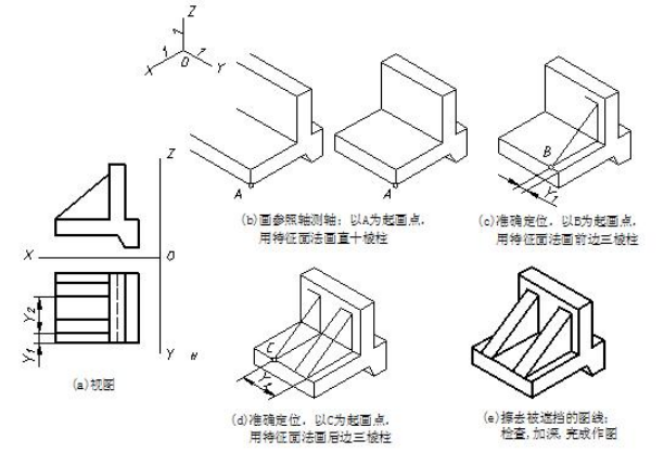
                              图7-5 用叠加法画物体正等测的示例 samples of superposition method

3.切割法 cutting method

       切割法用于画切割体轴测图。切割法画轴测图的思路是:先画出原体,然后通过“移线”,的方法依次画出切割处。切割时一定要注意切割位置的确定。

       The cutting method applies to make axonometric drawing of cutting solids. The idea is to draw the original solid, and then cut the solid based on given views. One should determine the cutting position during cutting solid away from the original solid.

       图 7-6 所示是用切割法画轻型桥台上部正等测的作图步骤。该物体的原体可看成是直六棱柱,在前面居中上下切出一个倒置的半四棱台孔。应先画出原体直六棱柱,再按孔的位置通过移线画出孔,完成作图。

       The solid in the example can be regarded as a prism and cut a frustum of rectangular pyramid away the prism. The steps described are as follows.

                               图7-6 用切割法画物体正等测的示例 sample of cutting method

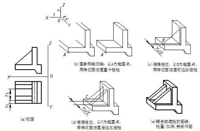
图7-7 用叠加法画物体斜二测的示例 sample of superposition method