平面的投影 SECTION THREE PROJECTION OF PLANES
一、平面投影图的画法 construction of planes
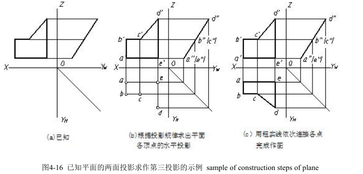
画平面投影图的方法一般是:先画出各顶点的投影,然后将它们的同面投影依次连接。如图 4-16 所示,是已知平面的两面投影求第三投影的作图过程。
As we all know, any surface is surrounded by line segments, meanwhile, any line segment is made up of points. Thus, one can draw the projection of each point of the surface, and then connect the projections of the points in the same projection plane and as shown in fig 4-16.
Step1. Analyze the given conditions.
Step2. Mark the projection of front view in order.
Step3. Find out the projection of every point in the connecting line.
Step4. Follow the projection rule to get the third projection of points.
二、各种位置平面的投影特性 Projection characteristics of different position planes
在三投影面体系中,平面的位置分为三类:一般位置平面、投影面平行面、投影面垂直面。后两类统称为特殊位置面。
The relative positions of a plane in the three-view projection system can be classified into general planes, parallel planes and perpendicular planes. The last two are called special position planes.
1.一般位置平面 general position planes
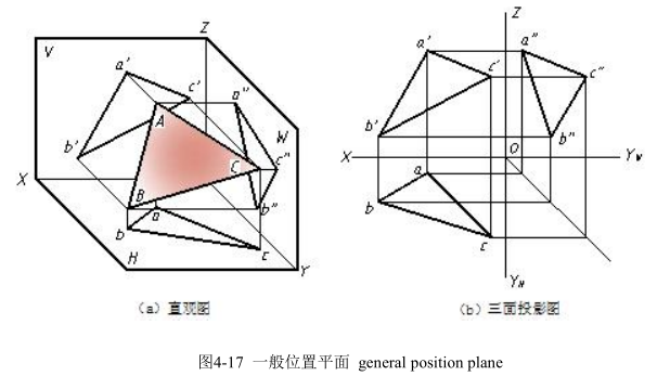
相对三投影面都倾斜的平面称为一般位置平面,如图 4-17 所示。平面对 H、V、W三投影面的倾角分别用α、β、γ表示。
一般位置平面的投影特性是:三投影均为类似形,而且不反映该平面与投影面的倾角。
Position: the plane is oblique to three projection planes.
Projection: three similar shapes of object. The similar shapes cannot show the true shape of plane because the plane does not parallel the projection planes.
Decision condition: one can work out the third projection of surface based on the given projection and follow the projection rules of points.
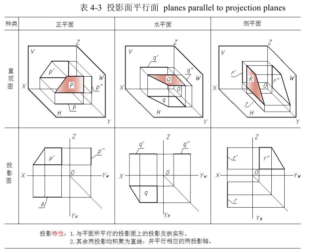
2.投影面平行面 planes parallel to projection planes
平行于一个投影面,垂直于另外两个投影面的平面称为投影面平行面。投影面平行面分三种:
正平面 —— 平行于 V 面,垂直于 H、W 面;
水平面 —— 平行于 H 面,垂直于 V、W 面;
侧平面 —— 平行于 W 面,垂直于 V、H 面。
各种投影面平行面的直观图、三投影图及投影特性见表 4-3。
Position: if there is a face which parallel one projection plane, it must be perpendicular to the other two projection planes.
Projection: following the theory of orthographic projection, one can obtain the true shape of plane in the parallel projection plane and get two straight line segments in the other two perpendicular projection planes.
There are three situations of planes parallel to projection planes .
V- Parallel plane (parallel VP and set at right angle to the other two PP)
H-parallel plane (parallel HP and set at right angle to the other two PP)
W- Parallel plane (parallel AVP and set at right angle to the other two PP)
Projections and pictorial drawings of planes parallel to projection planes are as follows in table 4-3.
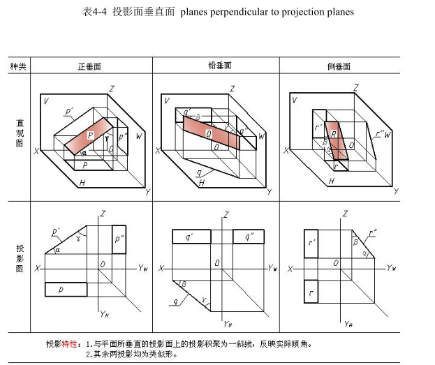
3.投影面垂直面 planes perpendicular to projection planes
垂直于一个投影面,倾斜于另外两个投影面的平面称为投影面垂直面。投影面垂直面也分三种:
正垂面 —— 垂直于 V 面,倾斜于 H、W 面;
铅垂面 —— 垂直于 H 面,倾斜于 V、W 面;
侧垂面 —— 垂直于 W 面,倾斜于 V、H 面。
各种投影面垂直面的直观图、投影图及投影特性见表 4-4。
Position: assume that a plane is perpendicular to one PP and oblique to the other two PP.
Projection: following the theory of orthographic projection, one can obtain one oblique line segment and gets two similar shapes of the plane in the oblique PP.
Planes perpendicular to projection planes can be classified into three situations.
V- perpendicular plane (⊥VP and oblique to the other two PP)
H-perpendicular plane (⊥HP and oblique to the other two PP)
AVP- perpendicular plane (⊥AVP and oblique to the other two PP)
Projections and pictorial drawings of planes perpendicular to projection planes are as follows in table 4-4.
比较三类平面的投影特性可以看出:
平面的投影中有一投影积聚为一斜线,即为投影面的垂直面;平面的投影只要有一个积聚为平行投影轴的直线,即为投影面的平行面;平面的三个投影均为类似图形,为一般位置平面。
Tips: one can produce the third projection of plane based on two projections quickly and correctly. The understanding of similar shape is very important for one during working out the projection of plane.
三、平面上的直线和点 property of subordination. Points and lines on planes
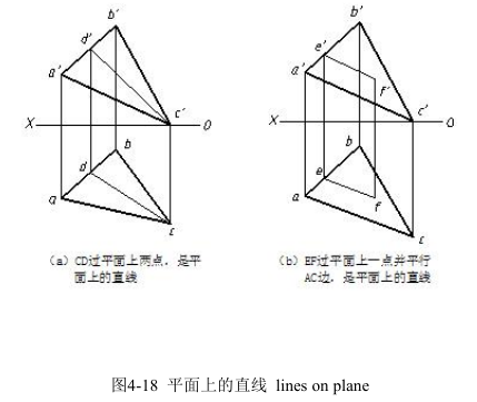
1.平面上的直线 lines on plane
由几何学可知直线在平面上的条件是:如果一直线通过平面上的两点,或者通过平面上的一点且平行于平面上的另一直线,则此直线必在该平面上,如图 4-18 所示。
2.平面上的点 points in plane
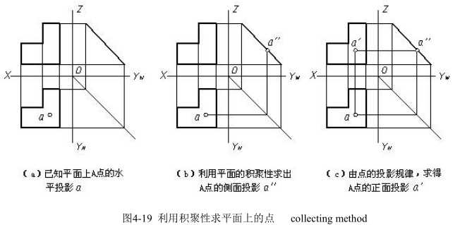
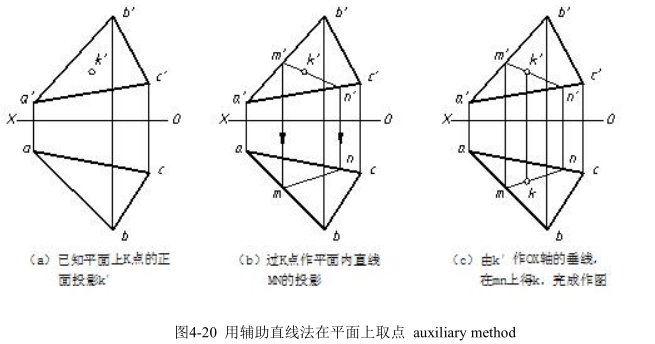
点在平面上的几何条件是:点在平面内的任一直线上,则该点必在此平面上。在平面上取点,特殊位置平面可利用积聚性直接求,作图步骤如图 4-19 所示。一般位置平面应先在平面上作一条辅助直线,然后在辅助直线的投影上取得点的投影。这种作图方法称为辅助直线法。用辅助直线法在平面上取点的作图步骤如图 4-20 所示。
If a point is located in any line of plane, it is sure the projection of point must be on the plane.Assume a point is on the special position plane, one can apply to collecting feature to work out the projection of point and the construction steps are as follows in 4-19. However , if a point on a general plane, the solution is to draw an auxiliary[ɔ:gˈzɪliəri]line through the point and make sure the line is on the plane , and then figure out the projection of the aided line ,finally get the projections of point. The method is of using auxiliary line on plane and steps are as shown in fig4-20.