
平面体与曲面体的相贯线 SECTION THREE INTERSECTION OF PLANNAR AND CURVED SOLIDS
一、平面体与曲面体相贯线的形状 SHAPE OF INTERSECTION
平面体与曲面体相交所产生的相贯线形状与平面截切曲面体的截交线形状相同,一般为平面曲线或组合线。
The intersection is the same as the intersection of a plane and a curved solid and it is always planar curve or combination line.
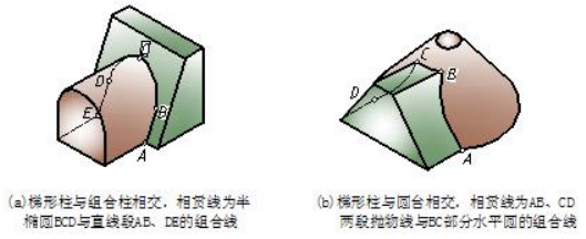
图5-1 平面体与曲面体相贯线形状的分析 fig 5-1 shape analysis of intersection
二、平面体与曲面体相贯线的画法 construction of intersection
平面体与曲面体的相贯线与平面截切立体所产生的交线形状相同,因此,求画相贯线的方法也类同。
The intersection of polyhedral solid and curved solid is the same as the intersection of a plane and a curved solid so is the construction method.
【例 5-1】图 5-2(a)所示圆台与三棱柱相交,求画相贯线的投影,完成三视图。
【Eg.5-1】please draw the intersection and complete the three views . A frustum of a cone intersects with a triangular prism as shown in fig 5-2 (a).
分析 analysis
圆台与三棱柱相交实质上是圆锥面与三棱柱上斜面相交,所产生相贯线的形状是椭圆的一部分,相贯线上有 A、B 两个特殊点,如图 5-2(b)所示。相贯线的侧面投影与斜面的积聚投影重合;水平投影和正面投影为类似形,需求画。该相贯线应从已知的侧面投影入手找点,然后看成圆台表面上的点来求画。
The shape of intersection is a part of ellipse. There are two special points in it as shown in fig 5-2(b). Its side vertical projection is coincides with the projection of the prism's side face; its horizontal and vertical projections are both similar figures and need to figure out. The thinking should find points in the left view and then work out the points on the frustum of a cone.
作图 construction
作图步骤如图 5-2(c)所示。该相贯线应先求特殊点,再求中间点。
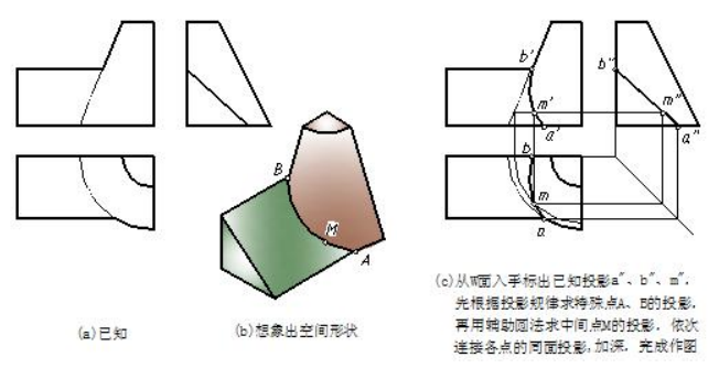
图5-2 圆台与三棱柱相交相贯线的画法示例
作图步骤如图 5-2(c)所示。该相贯线应先求特殊点,再求中间点。
Drawing steps are shown in fig 5-2(c).special points should be found out first, then intermediate points.
Step one: read the given views.
Step two: imagine the solid in space based on the known views.
Step three: mark the special and general points in the left projection of intersection.Work out the projections of special points and follow the projection rules.Get a general point in the left projection and turn to get point on the surface of frustum of a cone. Auxiliary circle is introduced here. Join all the points with smooth line and deepen drawing.
【例 5-2】图 5-3(a)所示护坡(直棱柱)与翼墙(组合柱)相交,求画相贯线的投影,完成三视图。
【Eg.5-2】please draw the intersection and complete the three views . A slope (prism) intersects a wing wall (composite column) as shown in fig 5-3(a).
分析 analysis
如图 5-3(b)所示,护坡与翼墙平面段的交线 A、B 是直线段,与翼墙曲面段(四分之一圆柱面)的交线 BMC 是平面曲线(四分之一椭圆),椭圆段交线上有 B、C 两个特殊点,即直线段相贯线是护坡斜平面与翼墙外平面的共有线,所以直线段相贯线的水平投影和侧面投影分别与它们的积聚投影重合;正面投影为直线,需求画。椭圆段相贯线是护坡斜平面与翼墙圆柱面的共有线,相贯线的侧面投影和水平投影也与这些面的积聚投影重合,正面投影为类似形,需求画。
According to the known views, a prism intersects a composite column. The intersection is a composite line and it includes a line segment and a curve. Point A and point B are in the line segment and point B and point C are two special points in the curve. The left and top projection of intersection is known so just mark the points in the horizontal projection and collect in the left projection. It is easy to work out vertical projection based on projection rules.
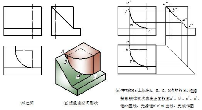
图5-3 护坡与翼墙相交相贯线的画法示例 sample of intersection between slope and wing wall
作图 drawing steps
作图步骤如图 5-3(c)所示。求直线相贯线 AB 只需找两端点,求该椭圆段相贯线应先求全特殊点,再求一个中间点确定曲线的曲率方向。
Step one:understand the known conditions.
Step two:imagine the solid in space based on the given views.
Step three:label the special and general points in the left or top projection of intersection.
Work out the projections of special points and follow the projection rules.
Drawing steps are shown in fig 5-3(c).special points should be found out first, then intermediate point determines the curvature [ˈkɜ:vətʃə(r)] direction.
应指出,由已知条件补画相贯线视图的思路是:
It should point out the thinking of completing the intersection is as follows.
(1)看懂相交两立体的形状。根据相交两立体的形状和位置判断出相贯线的空间形状。
(2)分析相贯线的投影。想象出相贯线各面投影的形状,确定已知,找出待求。
(3)画图。首先画出相交两立体,然后逐一求画各条相贯线,即“先体后线”。
Understand the given views and can figure out the shape of solids.Make sure the shape of intersection and determine the method to work out the intersection.Complete the drawing. First give the views of two solids and then work out the intersections one by one. In other words, follow the rule of solids first, then intersections.

