水利工程制图

武心嘉、汪艳芳

目录

  • 1 制图基本知识 Basic Knowledge of Drawing
    • 1.1 绪论 Introduction
    • 1.2 制图工具及其用法 Drawing Tools and Their Utilization
    • 1.3 国家标准有关规定 Related Provisions in National Standards
    • 1.4 几何作图geometric construction
    • 1.5 平面图形的绘制 The drawing of plane graphics
  • 2 投影的基础知识 The basics of projection
    • 2.1 投影法和投影特性 Projection method and projection properties
    • 2.2 工程中常用的四种投影图Four kinds of projection drawings commonly used in engineering
    • 2.3 物体的三面投影图 Three-sided projection of an object
  • 3 点线面的正投影 Projection of point、line and plane
    • 3.1 点的投影 Projection of Point
    • 3.2 直线的投影 Projection of Line
    • 3.3 平面的投影 Projection of Plane
    • 3.4 直线与平面、平面与平面的相对位置The position of a line relative to a plane, plane relative to a plane
  • 4 立体 Stereoscopic
    • 4.1 平面体的投影Projection ofProjection of  Planar Solids
    • 4.2 平面立体表面上的点和线 Points and lines on a planar solid surface
    • 4.3 平面立体截交线Plane stereo intersection line
    • 4.4 曲面立体的投影Stereoscopic projection of a curved surface
    • 4.5 曲面立体表面上的点和线Points and lines on the surface of a curved surface
    • 4.6 曲面立体的截交线Curved solid intersection
  • 5 立体表面相交Intersections of solids
    • 5.1 概述Overview
    • 5.2 两平面立体相交Two plane solids intersect
    • 5.3 平面体与曲面体相贯Intersections Between Planar and Curved Solids
    • 5.4 两曲面体的相贯线 The intersecting line of two curved bodies
    • 5.5 常见两曲面立体相贯线的讨论Discussion on the intersecting line of two surfaces
  • 6 组合体 composite solid
    • 6.1 组合体构成分析 Composition analysis
    • 6.2 组合体视图的画法 Composition View
    • 6.3 组合体的尺寸标注 The dimension of the assembly
    • 6.4 组合体视图的阅读 Reading the composite view
  • 7 轴测图的画法  construction of axonometric drawing
    • 7.1 轴测图的基本知识 Basic Knowledge
    • 7.2 平面体的正等测 Isometric Drawing
    • 7.3 平面体的斜二测 Cabinet Drawing
    • 7.4 曲面体的正等测 Isometric Drawing of Curved Solids
    • 7.5 曲面体的斜二测 Cabinet Drawing of Curved Solids
  • 8 工程形体的表达方法Expression methods of engineering objects
    • 8.1 视图 Views
    • 8.2 剖视图 Section View
    • 8.3 断面图 Cross Section
    • 8.4 简化画法和规定画法Simplified and prescriptive drawing
    • 8.5 视图的综合运用 Comprehensive use of views
    • 8.6 补充
  • 9 水工建筑物中常见的曲面 Curved surfaces in water conservancy project
    • 9.1 概述
    • 9.2 椭圆柱和椭圆锥
    • 9.3 双曲抛物面
    • 9.4 组合面Combination of surface
  • 10 标高投影 Projection with heights
    • 10.1 点、直线、平面 Points, lines, planes
    • 10.2 两平面的交线
    • 10.3 曲面和地形面 Curved and topographic surfaces
    • 10.4 标高投影在工程中的应用Application in engineering
  • 11 水利工程图 Hydraulic drawing
    • 11.1 水工建筑物和水工图 Hydraulic structures and drawings
    • 11.2 水利工程图表达 Expression of Hydraulic Engineering Drawing
    • 11.3 水工图的尺寸标注 Dimensioning of hydraulic drawings
    • 11.4 水工图的绘制 Drawing of hydraulic drawings
    • 11.5 水工图的阅读 Reading of hydraulic drawings
  • 12 建筑施工图Building construction drawing
    • 12.1 概述Overview
    • 12.2 建筑总平面图General plan of the building
    • 12.3 建筑平面图Construction plan
    • 12.4 建筑立面图 Elevation of Building
    • 12.5 建筑剖面图Building profile
    • 12.6 建筑详图 Architectural detailed drawing
组合体视图的画法 Composition View

【例 6-3】识读图6-3 (a)所示三视图,想象出该物体的立体形状。

Please imagine the simple solid based on the given views.

分析 analyze

① 识视图、分部分。先识视图后分部分,看主视图有三个线框,对应左视图各线框都是凸出来的部分,可知该物体是由三个基本体叠加形成,如图 6-3 (a)所示。

Analyze views and divide wireframes. Divide the front view into three wireframes and judge the simple solid is made of three basic solids as shown in fig 6-3 (a).

② 逐部分对投影、想形状。先看主视图第“1”部分矩形线框,根据投影规律对应俯视图和左视图,该部分的投影都是矩形线框,由基本体三视图图形特征可判定该部分形体是长方体;同理分析第“2”部分组合线框,对应两个矩形线框,形体为组合柱;看第“3”部分三角形线框,对应两个矩形线框,形体为三棱柱,如图 6-3 (b)所示。

Find out projection of each part and imagine basic solids. The front view of part is a rectangle and the other two views are both rectangles based on projection rules.According to projection characteristics of basic solid, the basic solid of part 1 is a box. the solid of part 2 is a composite column because its front view is a composite frame and the other two views are both rectangles; the solid of part 3 is a triangular prism in the same way.

③ 综合起来想整体。由主视图可看出,组合柱和三棱柱均在长方体之上,并左右居中;由左视图可看出,组合柱在后,三棱柱在前,组合柱与长方体后边靠齐,整体形状如图 2-1(c)所示。

Combination the overall simple solid based on relative positions among the three basic solids. From the front view can be seen that the composite column and the prism on the top of the box and  locate in the middle; from left view can be seen that column in back and prism in front, composite column and the box alignment in back. The overall shape is as shown in Figure 2-1 (c).

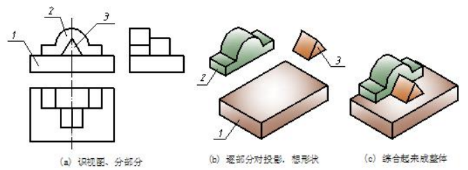
                    图 6-3  叠加式简单体三视图的识读示例 Reading sample of superposition solid

【例 6-4】识读图 6-4 (a)所示三视图,想象出该物体的立体形状。

Please make the solid in space based on the given views.

分析 analyze

① 识视图、分部分。先识视图后分部分,看三个视图中的小线框都套在大线框内,可以判定该物体是由基本体切割形成,分部分时,应先把原体分为一部分,然后再分切割处。各视图中大线框就是原体的投影,分为第“1”部分,另有两处切割,共分三部分,如图 6-4 (a)所示。

② 逐部分对投影、想形状;综合起来成整体。先看第“1”部分原体,三视图均为矩形是长方体,如图6-4 (b)所示;看第“2”部分,三角形线框对应两个两矩形线框,即在原体的左上前角切去了一个三棱柱,如图 2-2(c)所示;看第“3”部分,U 形线框对应两个矩形线框,即在原体的右边上下正中挖了一个 U 形通槽,综合起来即为整体,如图 6-4 (d)所示。

Analyze the given views and divide the front view into three wireframe. Because the wireframe of part 1 includes part 2 and part 3, one can regard the simple solid is a cutting solid. The original solid is a box then subtract two basic solids.Find out projections of three parts and imagine solid one by one. Part 1 is a box, part 2 is a triangular prism, and then, the part 3 is a composite column  respectively. Combine the overall cutting solid. The procedure of producing solid is as following. 

Step1. work out an original solid as to the known views.As for the example, one can regard it as a box based on the three rectangles.

Step2. cut a triangular prism away based on the front view.

Step3. cut a composite column away based on the front view.

Step4. check the solution and the three views.

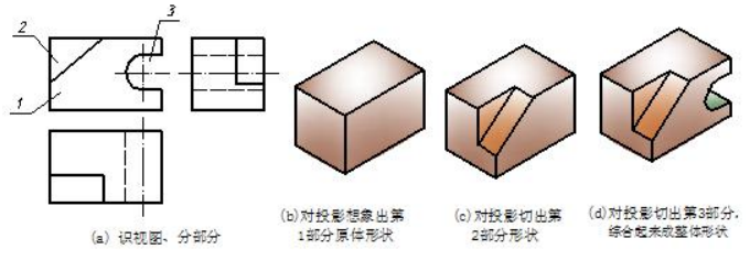
                         图6-4 切割式简单体三视图的识读示例  Fig 6-4 reading sample of cutting solid