视图 Views
一、基本视图
工程形体向六个基本投影面投影所得的视图,称为六个基本视图。
The views obtained by projecting the engineering body onto the six basic projection planes are called the six basic views.
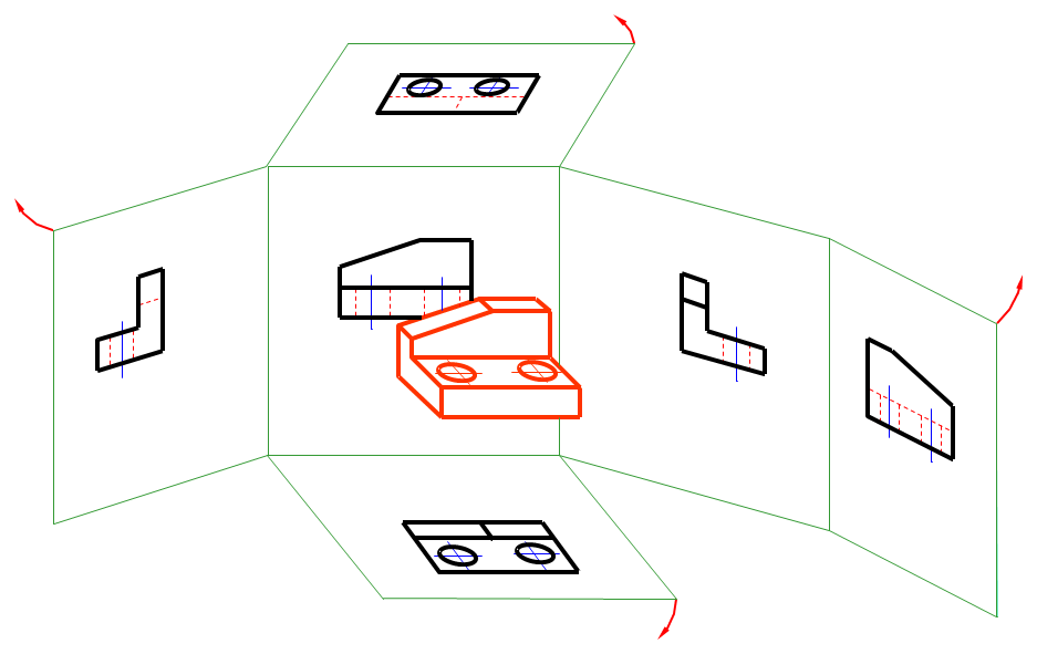
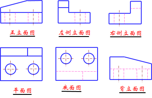
六个基本视图的投影规律 Projection rules for the six basic views
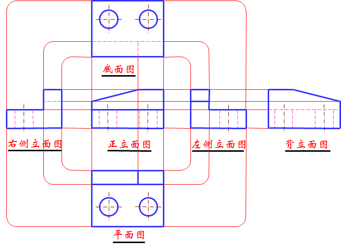
基本视图的投影规律:长对正;高平齐;宽相等。Projection law of basic view: long and straight; Gao Pingji; The width is equal.
工程上常用视图配置 Common view configuration on the project
二、辅助视图 Auxiliary view
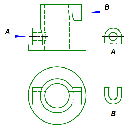
1、局部视图 Partial view:将形体的某一部分向基本投影面投影所得的视图。
(1) 局部视图的画法
a、断裂边界应用波浪线表示
b、当所表示的局部结构是完整的,且外轮廓线又成封闭时,波浪线可省略不画
(2)局部视图的配置
一般应按投影关系配置,有时也可放在其它适当位置。
(3) 局部视图的标注
一般都需要标注。
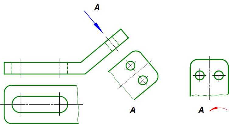
2、斜视图 Oblique view
形体向不平行于任何基本投影面的平面投影所得的视图,称为斜视图。 斜视图一般只表达机件倾斜部分的实形。其断裂边界以波浪线表示。
A plane projection that is not parallel to any of the basic projection surfaces.The oblique view generally expresses only the solid shape of the inclined part of the machine.The fracture boundaries are represented by wavy lines.
斜视图一般按投影关系配置,允许将斜视图的主要中心线或轮廓线旋转到水平或垂直位置。斜视图必须进行标注。
Strabismus is usually configured in a projection relationship, allowing the main center or outline of the strabismus to be rotated to a horizontal or vertical position.Strabismus must be marked.
1、斜视图的画法——斜视图一般只表达机件倾斜部分的实形。其断裂边界以波浪线表示。
2、斜视图的配置——斜视图一般按投影关系配置,允许将斜视图的主要中心线或轮廓线旋转到水平或垂直位置 。
3、斜视图的标注——斜视图必须进行标注。
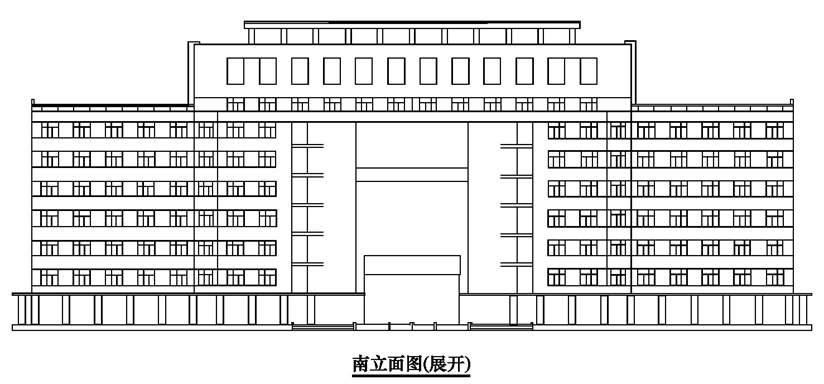
3、旋转视图 Rotate the view
当形体上具有倾斜部分时(如图带有倾斜侧翼的某办公楼 ),也可采用旋转视图反映该部分的实形。
When the body has an inclined part (as shown in the picture of an office building with an inclined wing), the rotating view can also reflect the solid shape of the part.
倾斜部分旋转到与中间部分同一平面内,然后作房屋的正立面图。展开视图的配置与基本视图的配置相同,但是必须在图名后加注“展开”。
The inclined part rotates into the same plane as the middle part, and then makes the front elevation of the house.The expanded view is configured the same as the base view, but must be followed by the word "expanded."
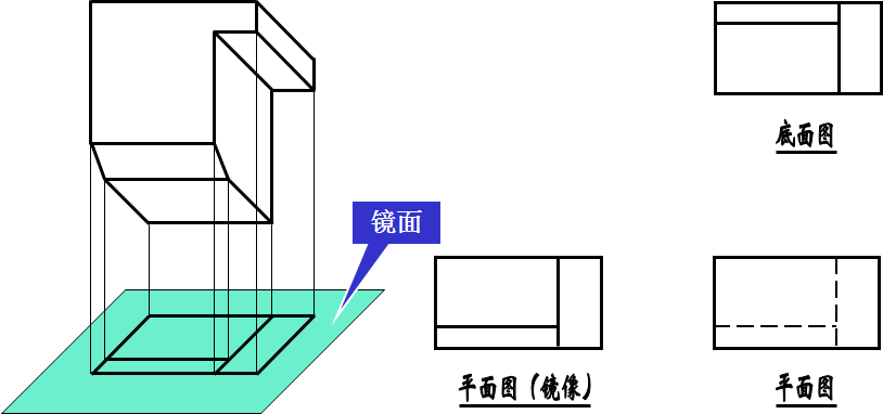
4、镜像视图 Image view
把镜面放在物体的下面,代替水平投影面,在镜面中反射得到的图像,称为“平面图(镜像)”。在图名后注写 “镜像”两字。
The image reflected in the mirror, which is placed under the object instead of a horizontal projection, is called a "plane map".After the name, write "mirror image".