
8.3 剖视图 Section View
一、剖视图的概念 Concept of section view
技术制图标准规定:假想用剖切面剖开物体,将处在观察者和剖切面之间的部分移去,而将其余部分向投影面投射所得的图形称为剖视图,可简称剖视。如图1所示。
Technical drawing regulates: an object is broken away by an imaginary cutting plane and removes the parts between the cutting plane and the observer, and then projects the rest on projection plane. In this way, one can obtain section of object.
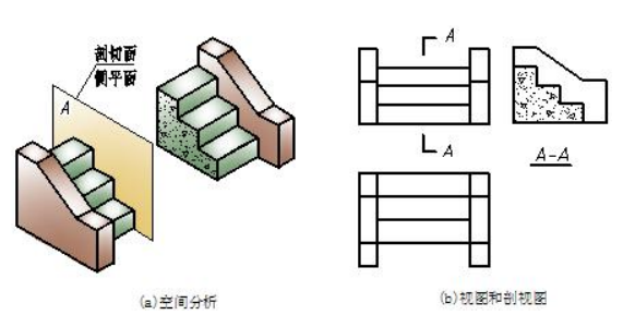
图1 剖视图的概念 Concept of section view
二、剖视图的画法与标注 Construction and label of section view
1.剖视图的画法 construction of section
以改画图2所示混凝土杯形基础主视图为剖视图为例,介绍剖视图的画法思路。
Change the front view of concrete cup foundation into section and introduce the drawing steps.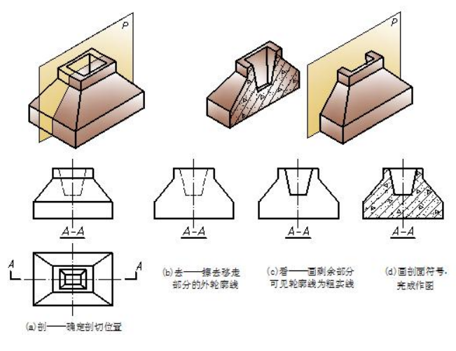
图2 剖视图的画法 construction of section
(1)剖。画剖视图,首先应确定剖切位置,在视图中应进行标注,如图2(a)所示。为了表达物体内部结构的真实形状,剖切面的位置一般应平行于投影面,且与物体内部结构的对称面或轴线重合。
(2)去。移去剖切面与观察者之间的部分,在视图中应擦去移去部分的外形轮廓线,如图2(b)所示。
(3)看。将剩余部分当成一个立体进行投射,在视图中将可见轮廓线全部画成粗实线,如图2(c)所示。
(4)画剖面符号。在剖切面与物体接触的部分画出剖面符号,本例剖面材料为钢筋混凝土,如图2(d)所示。
Step1. Cut the object with an imaginary plane (decide on the location of cutting)
Step2. Remove the parts between the cutting plane and the observer. (Erase some outline related to the removed part)
Step3. Project the rest on the projection plane. (Draw the visible part with wide continuous lines and omit some invisible outline)
Step4. Draw section symbols. (Draw section lining or cross hating with thin line)
2.剖视图的标注 Label of section
为了表达剖视图与有关视图之间的投影关系,便于读图,一般应加以标注。如图2所示,标注中应注明剖切位置、投射方向和剖视图的名称。
(1)剖切位置和投射方向。其用剖切符号表示,剖切符号是标明剖切面起、止和转折位置及投射方向的符号。剖切符号由剖切位置线和投射方向线组成一直角,均以粗实线绘制。剖切位置线的长度宜为 5~10mm,投射方向线的长度宜为 4~6mm。绘图时,剖切符号不宜与轮廓线接触。
(2)剖切符号的编号。其宜采用阿拉伯数字或拉丁字母,若有多个剖视图,应按顺序由左至右,由上至下连续编号,编号应写在投射方向线的端部,并一律水平书写。
(3)剖视图的名称。它与剖切符号的编号对应,剖视图的名称写在相应剖视图的下方(或上方),注出相同的两个字母或数字,中间加一条 5-10mm 长的细实线,如“A-A”、“1-1”。图名的字体应大一些。
(1) mark the location of cutting and projection sight ( a cutting plane line indicates where the imaginary cutting take place. The ends of the cutting plane line are bent at 90 degree and terminated by a segment to indicate the direction of sight for viewing the section)
(2)Mark of section( one can take Arabic numeral or Latin alphabet)
(3)Name of section ( section A-A )
3.画剖视图应注意的问题 Problems should be paid attention to during drawing section
(1)明确剖切是假想的。剖视图是假想把物体剖切开后所画的图形,除剖视图外,其余视图仍应完整画出。
(2)不要漏线。剖视图不仅应该画出与剖切面接触的断面形状,而且还要画出剖切面后的可见轮廓线。对初学者而言,往往容易漏画剖切面后的可见轮廓线,应特别注意。
(3)合理地省略虚线。用剖视图配合其它视图表示物体时,图上的虚线一般省略不画。但如果画出少量的虚线可以减少视图数量,而且又不影响视图的清晰时,也可以画出少量的虚线。
(4)正确绘制剖面材料符号。位置要正确,符号要规范,应注意同一物体各剖视图上的材料符号要一致,即斜线方向一致、间距目测相等。
(1)One should finish the other views completely except the section. As we know,the cutting does not exist.
(2)Remember to draw the visible outline behind the cutting plane.
(3)Omit long dash lines properly. Section view should ignore hidden lines in order to illustrate object more clearly. But if the hidden line would help to read views, it can be drawn.
(4)Draw cutting lining correctly.
三、剖视图的种类 Type of section view
在工程设计中,应根据工程形体的特点,选择适当的剖切方法和合理的剖切范围来表达内部结构。这样所绘制出的剖视图实际上是不同的剖切方法与不同种类剖视图的组合。下面介绍几种工程上常用的几种剖视图。
In engineering design, you should select the appropriate cutting method and the reasonable cutting range to express the internal structure based on the characteristics of engineering objects. Section views are actually a combination of different cutting methods and different section views. Here are several commonly used engineering section views introduced.
1.单一全剖视图(简称全剖视) Full Section View
用单一剖的方法把物体完全剖开后所得的剖视图称为单一全剖视图,如图1所示。
Full sections: when the cutting plane extends through the object in a straight line completely and removes the front half of object, a full section is obtained.This type of section is widely used to show both detail and assembly drawings.
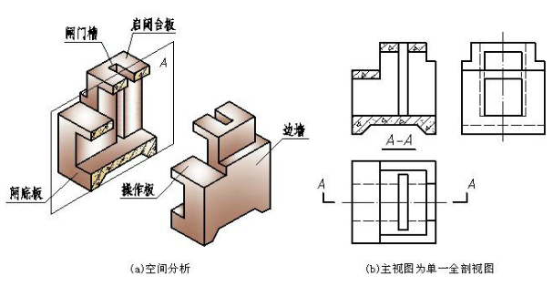
图1 单一全剖视图
图1所示为一钢筋混凝土闸室段,假想用一个平行于正立投影面的剖切平面,通过闸室的前后对称中心剖切,移去闸室的前半部分,将后半部分向正立投影面投射。剖切前,主视图中闸底板、闸门槽、启闭台板和操作板均为虚线,剖切后,这些部位的轮廓线均可见,用粗实线绘制出。前面的边墙剖切后被移去不画,后面边墙顶面的轮廓线,由于它在左视图中已表达清楚,在剖视图中可省略虚线。最后在断面上绘制出钢筋混凝土剖面符号,就得到了该闸室单一全剖的主视图。单一全剖视图一般要全标注。下面以补画钢筋混凝士闸室段单一全剖的左视图为例,介绍补画剖视图的画法要点。
The solid is a section of block chamber and its material is reinforced concrete. Now assume a vertical parallel projection plane along the symmetry line between the front and the back to divide the chamber into two parts. The rear part is kept and projects on the vertical projection plane. It is obvious the contours of the bottom plate, gate slot, operation panel are invisible before cutting. After cutting, all these dash lines change into visible lines so they should be drawn with thick solid lines. One should notice the front wall is removed. so we dont need to show it. Finall my remember to draft section symbols on the section face to get a section finished.
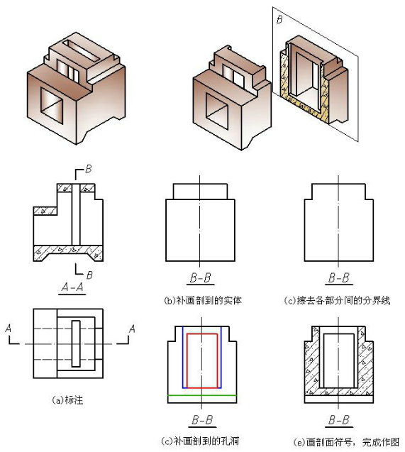
图2 补画剖视图的画法示例 samples of completing the section
(1)标注。确定剖切位置和投射方向,如图2(a)所示。
(2)补画剖到的实体。像补视图一样,逐一补画出剖到(即与剖切面接触)的实体部分。本例为2部分,如图2(b)所示。
(3)擦去各部分间的分界线。将补画出各实体间的分界线擦去(因为共面),只保留剖到的外轮廓,如图2(c)所示。
(4)补画剖到的切割部分。逐一补画出切断面上的切割部分。本例切断面上的切割部分有过水的大矩形孔洞,闸门槽、闸底板上的梯形槽(齿墙结构)3 部分,如图2(d)所示。
(5)画剖面符号。在剖到的实体部分画出剖面符号。本例剖面材料为钢筋混凝土,如图2(e)所示。
注意:最后应检查剖切面后是否还另有可见部分,其可见部分也应用粗实线画出。
First step: label and determine the cutting location and projection direction.
Second step: complete the cutting parts.
Third step: erase the boundary lines.
Fourth step: complete other details
Last step: draw section symbols.
Tips : check the section and don't forget the visible outlines of the right part.
2. 半剖视图 Half sections
Half sections:a symmetrical object may be drawn as a half section, one half in sections and the other half in full view. A normal center line is used to divide them.This type of section is used mostly for drawings where internal and external features areclearly shown.
3. 阶梯剖视图 Offset sction view
Offset sections: in order to show features that are not in a straight line, the cutting plane may be offset or bent, so as to include several cutting planes.An offset section is similar to a full section in that the cutting plane extends through the object from one side to the other.
Note: it doesn't need to draw section line on the change location.

