
曲面体正等测轴测图的画法 SECTION THREE AXONOMETRIC PROJECTION OF CURVED SOLID
曲面体轴测图的画法思路与平面体相同,掌握物体上圆的画法是绘制曲面体轴测图的关键,掌握基本曲面体轴测图的画法是绘制曲面体轴测图的基础。常用的基本曲面体是底面平行坐标面的圆柱、圆台(锥)。
Polyhedral solids and revolution solids have the same principle of constructing axonometric projection. To grasp the construction of circles of object is the key point. With the use of the construction of some basic revolution solids, one can finish axonometric drawing of complicated(复杂的) curved solids. The basic solids commonly used are cylinder, cone whose base planes are parallel to projection planes
一、曲面体正等测的画法 isometric drawing of curved solids
1.底面平行坐标面的基本体正等测的画法 Basic planes parallel to coordinate planes
绘制底面平行坐标面的圆柱、圆台(锥)的正等测的方法是:先画出两底面圆,再做出两底面的公切线表示柱面或锥面。由于正等测各坐标面都倾斜于轴测投影面,所以平行于各坐标面圆的正等测都是椭圆。画正等测中平行于坐标面的底面圆,一般采用菱形法。菱形法是用四段圆弧近似画出椭圆,它只适用于正等测。图 7-10 所示是水平圆柱(底面为水平面)正等测的画图步骤。
先画圆柱的可见底面。以圆底面中心为起画点,根据图 7-10(a)所示圆柱底面的方位,平行相应的轴测轴画圆的中心线;然后根据圆的半径定出一对共轭直径的端点 A、B、C、D,过这四个点画圆的外切正方形的正等测菱形,A、B、C、D 为椭圆与菱形各边的切点;过切点作菱形各边的垂线得四个交点 1、2、3、4,即为四段圆弧的圆心;分别以 1、2 为圆心,1B 为半径,画 BC、AD 圆弧,再分别以 3、4 为圆心,3A 为半径画AB、CD 圆弧,完成上底面,如图 7-10(b)所示。再依次画轴线定出下底面圆心,用菱形法画下底面,作上、下底面公切线,擦去不可见轮廓线及辅助线,加深,完成作图,如图 7-10(c)、(d)、(e)所示。
The method is to draft the isometric drawing of two bases, and then add the connecting straight lines on the outside of the profile (轮廓,外形).When the circular base plane is parallel to coordinate plane, the isometric drawing has the shape of an ellipse. An approximate method is commonly introduced to draw isometric circles in each of the three major planes. In this way, an approximate ellipse can be easily developed with drawing compasses. The precision is adequate for pictorial drawing. Take a horizontal circle as an example to explain the construction steps.
Step1. Draw isometric axes of ox and oy .
Step2. Make the radius along the center lines. Draw parallel lines through the four points respectively.
Step3. Work out center points of four arcs in every case.
Step4. Draw arcs respectively and darken the drawing.
The isometric drawing of circles parallel to the other two projection planes has the same process as the above.
Example1. Produce the isometric drawing of object based on the given views.
Analysis of the views:
A cylinder can be judged from the given views. Its bases are parallel to the HP. Follow the principle mentioned above to produce the isometric drawing of the circle of top plane. Move the center points down along the axis of oz with the distance of the height of cylinder and finish arcs with the same radius in every case. Add the leftmost and rightmost generating line.
Step1. Draw the center lines.
Step2. Finish the ellipse of top plane.
Step3. Finish the ellipse of bottom plane.
Step4.Add the connecting lines.
Step5. Darken the drawing and erase all unnecessary lines.
The isometric drawing of cylinder parallel to the other two projection planes has the same process as the above.
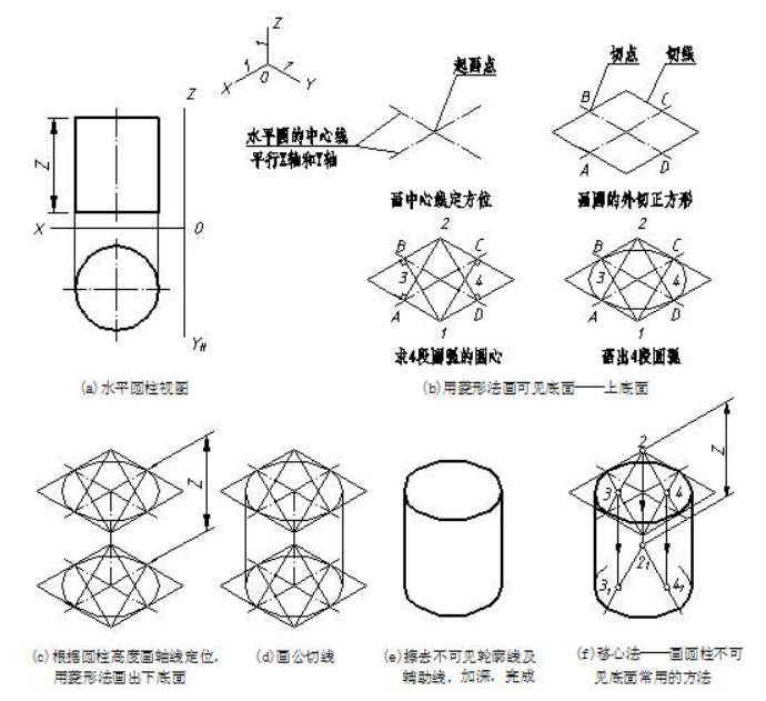
图7-10 水平圆柱正等测的画图步骤 Drawing steps of cylinder whose axis is perpendicular to horizontal projection plane
为了减少作图线,画圆柱下底面三段可见的圆弧时,可以从上底面的各圆弧的圆心(2、3、4)沿轴线方向量取圆柱两底面间距,直接得到下底面三段圆弧的圆心,然后用相应的半径画出下底面三段圆弧,这种作图方法称为“移心法”,如图 7-10(f)所示。图 7-11 所示是正平圆柱(底面为正平面)和侧平圆柱(底面为侧平面)的正等测,画法与上相同,可见底面用菱形法绘制,不可见底面用移心法画出。
In the same construction steps, one can get isometric drawings of cylinder whose axis is perpendicular to vertical projection plane or side vertical projection plane. The visible surface is drawn with diamond method and invisible face is drawn by shifting the center points.
同上方法可绘制圆台(或圆锥)的正等测,只是两底面大小不同(或一个是锥尖),不能应用移心法。
In the same way, one can draw isometric drawing of a cone or a cone’s frustum. As for them, the different size of two bases. However, one cannot apply to the method through moving the center points.
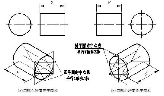
图7-11 正平圆柱和侧平圆柱的正等测图Isometric mapping of a straight cylinder and a lateral straight cylinder
2.应用举例 sample
【例】画出图 7-12(a)所示闸墩的正等测。 Complete the isometric projection of object with round corners.
Step1. build the box.
Step2. attempt to find out the tangency points and centers.
Step3. draw perpendicular lines through the tangency points and the intersection points are the centers of arcs.
Step4. follow the same way to draw cylinder and complete the drawing.
分析 analysis
闸墩是一个切割体,原体是上下底面为水平面的组合柱,右端切角,左端前后各切出一个长方体形门槽。用切割法画闸墩正等测,起画点宜选在组合柱上底面圆的圆心处。作图步骤如图 7-12(b)、(c)、(d)所示。
The pier is regarded as a cutting solid and the original solid is a composite column whose two bases are parallel to the horizontal projection plane. The right corner is cut away and subtracts a rectangular slot. One can choose the center point of top face of composite column as shown in fig.
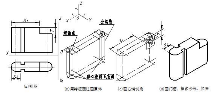
图7-12 闸墩正等测的画图步骤 construction steps of the pier
【例】画出图 7-13(a)所示物体的正等测。 Complete the isometric drawing of object.
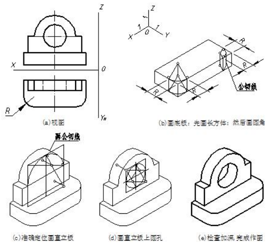
图7-13 曲面体正等测的画法示例 round corner of curved solids
分析 analysis
该物体是一个既有叠加又有切割的综合体,由底板和直立板两部分叠加,底板上有两个圆角,直立板上挖了一个圆通孔,画该物体的正等测应综合运用上述方法。作图步骤如图7-13(b)、(c)、(d)、(e)所示。
The solid is combined with superposition and cutting. Its base consists of two basic solid. They are both composite columns. The steps are as follows.
作图时应注意以下两点:
(1)画底板的圆角时,应在作圆角的边上量取圆角半径 R 得切点,过切点作边线的垂线,然后以两垂线的交点为圆心,以圆心到切点的距离为半径画弧,即为上底面圆角正等测;再用移心法画出下底面圆角,然后画出上下底面圆角的公切线。
(2)直立板圆孔后壁的圆是否可见,这将取决于孔径与板厚之间的关系。若直立板厚小于椭圆短轴,则后面的圆可见,反之为不可见。
Construction should pay attention to the following two points:
(1) Fillet edge should be in the amount of radius R and get two tangent points. Make perpendicular lines through points of tangency in every case. The intersection of two lines is the center point. Draw arc with the radius from center point to the tangent points.in the same way, construct the bottom fillet.
(2) Whether the rear hole is visible or not, depends on the radius and the thickness of the board.

