水利工程制图

武心嘉、汪艳芳

目录

  • 1 制图基本知识 Basic Knowledge of Drawing
    • 1.1 绪论 Introduction
    • 1.2 制图工具及其用法 Drawing Tools and Their Utilization
    • 1.3 国家标准有关规定 Related Provisions in National Standards
    • 1.4 几何作图geometric construction
    • 1.5 平面图形的绘制 The drawing of plane graphics
  • 2 投影的基础知识 The basics of projection
    • 2.1 投影法和投影特性 Projection method and projection properties
    • 2.2 工程中常用的四种投影图Four kinds of projection drawings commonly used in engineering
    • 2.3 物体的三面投影图 Three-sided projection of an object
  • 3 点线面的正投影 Projection of point、line and plane
    • 3.1 点的投影 Projection of Point
    • 3.2 直线的投影 Projection of Line
    • 3.3 平面的投影 Projection of Plane
    • 3.4 直线与平面、平面与平面的相对位置The position of a line relative to a plane, plane relative to a plane
  • 4 立体 Stereoscopic
    • 4.1 平面体的投影Projection ofProjection of  Planar Solids
    • 4.2 平面立体表面上的点和线 Points and lines on a planar solid surface
    • 4.3 平面立体截交线Plane stereo intersection line
    • 4.4 曲面立体的投影Stereoscopic projection of a curved surface
    • 4.5 曲面立体表面上的点和线Points and lines on the surface of a curved surface
    • 4.6 曲面立体的截交线Curved solid intersection
  • 5 立体表面相交Intersections of solids
    • 5.1 概述Overview
    • 5.2 两平面立体相交Two plane solids intersect
    • 5.3 平面体与曲面体相贯Intersections Between Planar and Curved Solids
    • 5.4 两曲面体的相贯线 The intersecting line of two curved bodies
    • 5.5 常见两曲面立体相贯线的讨论Discussion on the intersecting line of two surfaces
  • 6 组合体 composite solid
    • 6.1 组合体构成分析 Composition analysis
    • 6.2 组合体视图的画法 Composition View
    • 6.3 组合体的尺寸标注 The dimension of the assembly
    • 6.4 组合体视图的阅读 Reading the composite view
  • 7 轴测图的画法  construction of axonometric drawing
    • 7.1 轴测图的基本知识 Basic Knowledge
    • 7.2 平面体的正等测 Isometric Drawing
    • 7.3 平面体的斜二测 Cabinet Drawing
    • 7.4 曲面体的正等测 Isometric Drawing of Curved Solids
    • 7.5 曲面体的斜二测 Cabinet Drawing of Curved Solids
  • 8 工程形体的表达方法Expression methods of engineering objects
    • 8.1 视图 Views
    • 8.2 剖视图 Section View
    • 8.3 断面图 Cross Section
    • 8.4 简化画法和规定画法Simplified and prescriptive drawing
    • 8.5 视图的综合运用 Comprehensive use of views
    • 8.6 补充
  • 9 水工建筑物中常见的曲面 Curved surfaces in water conservancy project
    • 9.1 概述
    • 9.2 椭圆柱和椭圆锥
    • 9.3 双曲抛物面
    • 9.4 组合面Combination of surface
  • 10 标高投影 Projection with heights
    • 10.1 点、直线、平面 Points, lines, planes
    • 10.2 两平面的交线
    • 10.3 曲面和地形面 Curved and topographic surfaces
    • 10.4 标高投影在工程中的应用Application in engineering
  • 11 水利工程图 Hydraulic drawing
    • 11.1 水工建筑物和水工图 Hydraulic structures and drawings
    • 11.2 水利工程图表达 Expression of Hydraulic Engineering Drawing
    • 11.3 水工图的尺寸标注 Dimensioning of hydraulic drawings
    • 11.4 水工图的绘制 Drawing of hydraulic drawings
    • 11.5 水工图的阅读 Reading of hydraulic drawings
  • 12 建筑施工图Building construction drawing
    • 12.1 概述Overview
    • 12.2 建筑总平面图General plan of the building
    • 12.3 建筑平面图Construction plan
    • 12.4 建筑立面图 Elevation of Building
    • 12.5 建筑剖面图Building profile
    • 12.6 建筑详图 Architectural detailed drawing
曲面体的斜二测 Cabinet Drawing of Curved Solids

曲面体斜二测的画法 Cabinet Drawing Construction of Curved Solids

1.底面平行坐标面的基本体斜二测的画法

      绘制底面平行坐标面的圆柱、圆台(锥)的斜二测的方法思路与正等测相同,但绘制圆的方法不同。图 7-14 所示是三种位置圆柱的斜二测图。由于斜二测的 XOZ 坐标面平行于轴测投影面,所以正平圆柱的底面在斜二测中反映实形,可直接画出。水平圆柱及侧平圆柱的底面在斜二测中为椭圆,需运用“坐标法”画出,坐标法是先在视图上画出一组平行于坐标轴的辅助线,然后作出这些辅助线与圆周交点的轴测图,再光滑连成椭圆。

       As we know, one can obtain true size of oblique drawing when the plane is parallel to the V-Projection –Plane.. The oblique lines are shortened by one-half of their true length. Whenever possible, the face of the object with circles or arcs should be selected as the front face, so those curved surfaces can be easily drawn in their true shape. The feature makes it easy to draw axonometric drawing of curved solid whose face is placed parallel to the vertical projection plane. Most of the principles of isometric drawing can be used for cabinet drawings.

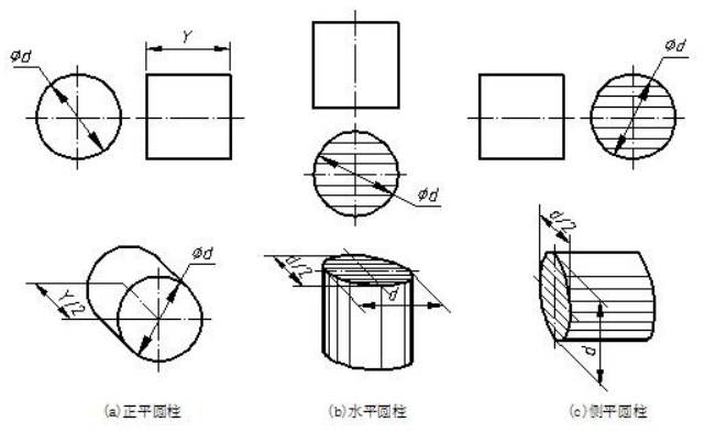
                                 图7-14 三种位置圆柱斜二测的画法 three situations of a cylinder

2.应用举例

【例】画出图 7-15(a)所示小桥的斜二测。Produce the cabinet drawing based on the given views.


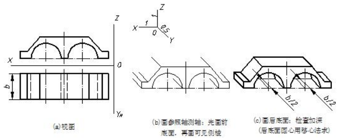
                                    图7-15 小桥斜二测的画法步骤 drawing steps of the bridge

分析 analysis

       小桥可看成是一个前后底面为正平面的组合柱,应先画出前底面的实形,再画出可见侧棱,然后画出后底面的可见轮廓线。作图步骤如图 7-15(b)、(c)所示。

       one can tell that the views represent a bridge. There are two semi-circles on the front face of object, so one can draw its oblique projection of front face then the back face. 

Step1. Copy the front view directly.

Step2. extrude the visible side edges and center lines with the distance of one-half thickness at 135°。

Step3. draw the visible parts of the two semi-circles.

Step4. connect the visible lines.

Step5. darken and clean the drawing.

Tips: one should determine the visibility of the outlines of the back face.

【例】画出图 7-16(a)所示八字翼墙出水口的斜二测。Draw the graph 3-16 (a) shown splayed wing wall outlet with cabinet projection.

分析 analysis

       该物体可看成是一个叠加体,由底板、八字翼墙和带孔的胸墙三部分组成,因为底板和翼墙同宽并且前后底面均为正平面,所以底板和翼墙两部分的斜二测可一起画。

       The object can be regarded as a superposition solid. It includes three parts, bottom plate, wing wall and parapet 英[ˈpærəpɪt]美[ˈpærəpɪt, -ˌpɛt]. because the bottom plate is as long as the wing wall and they are both parallel to the vertical projection plane, draw the two parts at the same time.

       作图步骤如图 7-16(b)、(c)、(d)、(e)所示。

       The drawing steps are as shown in 7-16(b)、(c)、(d)、(e)

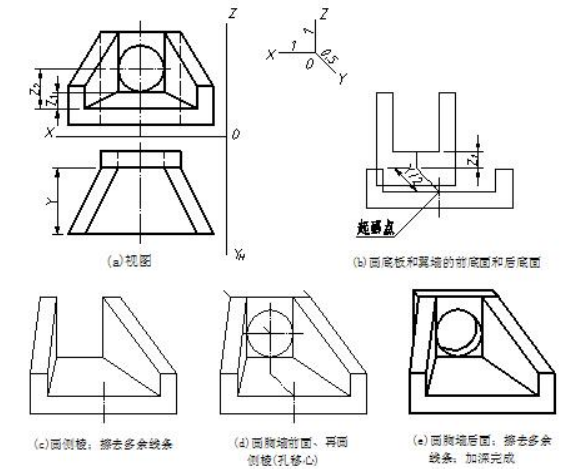
                       图7-16 八字翼墙出水口斜二测的画法步骤 construction steps of wing wall

画斜二测时应注意 : tips:

(1)Y 轴的轴向伸缩系数为 0.5,因此宽度方向尺寸要缩短一半。

Remember to change the width into half because of the coefficient 0.5.

(2)平行于 XOZ 坐标面的各平面形状,一般应从前向后依次完成。

It is better to draw faces which are parallel to the vertical projection plane from the front to the back.

(3)圆柱不可见底面的圆心,沿轴线方向用移心法求出比较简便。

It is convenient to finish invisible base of a cylinder with shifting the center point of arc or circle.