水利工程制图

武心嘉、汪艳芳

目录

  • 1 制图基本知识 Basic Knowledge of Drawing
    • 1.1 绪论 Introduction
    • 1.2 制图工具及其用法 Drawing Tools and Their Utilization
    • 1.3 国家标准有关规定 Related Provisions in National Standards
    • 1.4 几何作图geometric construction
    • 1.5 平面图形的绘制 The drawing of plane graphics
  • 2 投影的基础知识 The basics of projection
    • 2.1 投影法和投影特性 Projection method and projection properties
    • 2.2 工程中常用的四种投影图Four kinds of projection drawings commonly used in engineering
    • 2.3 物体的三面投影图 Three-sided projection of an object
  • 3 点线面的正投影 Projection of point、line and plane
    • 3.1 点的投影 Projection of Point
    • 3.2 直线的投影 Projection of Line
    • 3.3 平面的投影 Projection of Plane
    • 3.4 直线与平面、平面与平面的相对位置The position of a line relative to a plane, plane relative to a plane
  • 4 立体 Stereoscopic
    • 4.1 平面体的投影Projection ofProjection of  Planar Solids
    • 4.2 平面立体表面上的点和线 Points and lines on a planar solid surface
    • 4.3 平面立体截交线Plane stereo intersection line
    • 4.4 曲面立体的投影Stereoscopic projection of a curved surface
    • 4.5 曲面立体表面上的点和线Points and lines on the surface of a curved surface
    • 4.6 曲面立体的截交线Curved solid intersection
  • 5 立体表面相交Intersections of solids
    • 5.1 概述Overview
    • 5.2 两平面立体相交Two plane solids intersect
    • 5.3 平面体与曲面体相贯Intersections Between Planar and Curved Solids
    • 5.4 两曲面体的相贯线 The intersecting line of two curved bodies
    • 5.5 常见两曲面立体相贯线的讨论Discussion on the intersecting line of two surfaces
  • 6 组合体 composite solid
    • 6.1 组合体构成分析 Composition analysis
    • 6.2 组合体视图的画法 Composition View
    • 6.3 组合体的尺寸标注 The dimension of the assembly
    • 6.4 组合体视图的阅读 Reading the composite view
  • 7 轴测图的画法  construction of axonometric drawing
    • 7.1 轴测图的基本知识 Basic Knowledge
    • 7.2 平面体的正等测 Isometric Drawing
    • 7.3 平面体的斜二测 Cabinet Drawing
    • 7.4 曲面体的正等测 Isometric Drawing of Curved Solids
    • 7.5 曲面体的斜二测 Cabinet Drawing of Curved Solids
  • 8 工程形体的表达方法Expression methods of engineering objects
    • 8.1 视图 Views
    • 8.2 剖视图 Section View
    • 8.3 断面图 Cross Section
    • 8.4 简化画法和规定画法Simplified and prescriptive drawing
    • 8.5 视图的综合运用 Comprehensive use of views
    • 8.6 补充
  • 9 水工建筑物中常见的曲面 Curved surfaces in water conservancy project
    • 9.1 概述
    • 9.2 椭圆柱和椭圆锥
    • 9.3 双曲抛物面
    • 9.4 组合面Combination of surface
  • 10 标高投影 Projection with heights
    • 10.1 点、直线、平面 Points, lines, planes
    • 10.2 两平面的交线
    • 10.3 曲面和地形面 Curved and topographic surfaces
    • 10.4 标高投影在工程中的应用Application in engineering
  • 11 水利工程图 Hydraulic drawing
    • 11.1 水工建筑物和水工图 Hydraulic structures and drawings
    • 11.2 水利工程图表达 Expression of Hydraulic Engineering Drawing
    • 11.3 水工图的尺寸标注 Dimensioning of hydraulic drawings
    • 11.4 水工图的绘制 Drawing of hydraulic drawings
    • 11.5 水工图的阅读 Reading of hydraulic drawings
  • 12 建筑施工图Building construction drawing
    • 12.1 概述Overview
    • 12.2 建筑总平面图General plan of the building
    • 12.3 建筑平面图Construction plan
    • 12.4 建筑立面图 Elevation of Building
    • 12.5 建筑剖面图Building profile
    • 12.6 建筑详图 Architectural detailed drawing
组合体的尺寸标注 The dimension of the assembly

组合体尺寸标注 Assembly Size Marking

1.尺寸类别 Size categories

定形尺寸——确定组合体各组成部分形状大小的尺寸

定位尺寸——确定组合体各组成部分之间的相对位置的尺寸。

总尺寸——确定组合体总长、总宽、总高的尺寸。

2.尺寸基准 benchmark

组合体上标注定位尺寸时的起始位置(度量平面),在形体的长、宽、高三个方向有三个基准。

基准面一般选取形体的对称面、主要底面、顶面、端面或过回转体轴线的平面。

3.尺寸标注步骤 Dimensioning steps

1)分析组合体组成(形体分析);

2)确定尺寸基准,长、宽、高三个基准;

3)逐个形体标注确定该形体的定形尺寸;

4)从构成组合体要求考虑,标注各形体之间的定位尺寸;

5)标注组合体的总体尺す,并作局部调整。

4.尺寸标注要求 Dimensioning requirements

1)尺寸标注要完整:定形、定位、总尺寸齐全,尺寸基准明确。

2)尺寸标注要清晰:排列整齐,标注在特征视图上。

3)尺寸标注要合理:要便于度量和有利于保证制作精度。

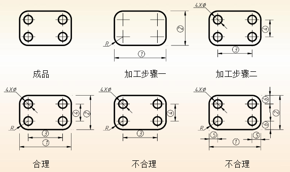
                                           图6-5 尺寸标注图例 Dimensional illustration