水利工程制图

武心嘉、汪艳芳

目录

  • 1 制图基本知识 Basic Knowledge of Drawing
    • 1.1 绪论 Introduction
    • 1.2 制图工具及其用法 Drawing Tools and Their Utilization
    • 1.3 国家标准有关规定 Related Provisions in National Standards
    • 1.4 几何作图geometric construction
    • 1.5 平面图形的绘制 The drawing of plane graphics
  • 2 投影的基础知识 The basics of projection
    • 2.1 投影法和投影特性 Projection method and projection properties
    • 2.2 工程中常用的四种投影图Four kinds of projection drawings commonly used in engineering
    • 2.3 物体的三面投影图 Three-sided projection of an object
  • 3 点线面的正投影 Projection of point、line and plane
    • 3.1 点的投影 Projection of Point
    • 3.2 直线的投影 Projection of Line
    • 3.3 平面的投影 Projection of Plane
    • 3.4 直线与平面、平面与平面的相对位置The position of a line relative to a plane, plane relative to a plane
  • 4 立体 Stereoscopic
    • 4.1 平面体的投影Projection ofProjection of  Planar Solids
    • 4.2 平面立体表面上的点和线 Points and lines on a planar solid surface
    • 4.3 平面立体截交线Plane stereo intersection line
    • 4.4 曲面立体的投影Stereoscopic projection of a curved surface
    • 4.5 曲面立体表面上的点和线Points and lines on the surface of a curved surface
    • 4.6 曲面立体的截交线Curved solid intersection
  • 5 立体表面相交Intersections of solids
    • 5.1 概述Overview
    • 5.2 两平面立体相交Two plane solids intersect
    • 5.3 平面体与曲面体相贯Intersections Between Planar and Curved Solids
    • 5.4 两曲面体的相贯线 The intersecting line of two curved bodies
    • 5.5 常见两曲面立体相贯线的讨论Discussion on the intersecting line of two surfaces
  • 6 组合体 composite solid
    • 6.1 组合体构成分析 Composition analysis
    • 6.2 组合体视图的画法 Composition View
    • 6.3 组合体的尺寸标注 The dimension of the assembly
    • 6.4 组合体视图的阅读 Reading the composite view
  • 7 轴测图的画法  construction of axonometric drawing
    • 7.1 轴测图的基本知识 Basic Knowledge
    • 7.2 平面体的正等测 Isometric Drawing
    • 7.3 平面体的斜二测 Cabinet Drawing
    • 7.4 曲面体的正等测 Isometric Drawing of Curved Solids
    • 7.5 曲面体的斜二测 Cabinet Drawing of Curved Solids
  • 8 工程形体的表达方法Expression methods of engineering objects
    • 8.1 视图 Views
    • 8.2 剖视图 Section View
    • 8.3 断面图 Cross Section
    • 8.4 简化画法和规定画法Simplified and prescriptive drawing
    • 8.5 视图的综合运用 Comprehensive use of views
    • 8.6 补充
  • 9 水工建筑物中常见的曲面 Curved surfaces in water conservancy project
    • 9.1 概述
    • 9.2 椭圆柱和椭圆锥
    • 9.3 双曲抛物面
    • 9.4 组合面Combination of surface
  • 10 标高投影 Projection with heights
    • 10.1 点、直线、平面 Points, lines, planes
    • 10.2 两平面的交线
    • 10.3 曲面和地形面 Curved and topographic surfaces
    • 10.4 标高投影在工程中的应用Application in engineering
  • 11 水利工程图 Hydraulic drawing
    • 11.1 水工建筑物和水工图 Hydraulic structures and drawings
    • 11.2 水利工程图表达 Expression of Hydraulic Engineering Drawing
    • 11.3 水工图的尺寸标注 Dimensioning of hydraulic drawings
    • 11.4 水工图的绘制 Drawing of hydraulic drawings
    • 11.5 水工图的阅读 Reading of hydraulic drawings
  • 12 建筑施工图Building construction drawing
    • 12.1 概述Overview
    • 12.2 建筑总平面图General plan of the building
    • 12.3 建筑平面图Construction plan
    • 12.4 建筑立面图 Elevation of Building
    • 12.5 建筑剖面图Building profile
    • 12.6 建筑详图 Architectural detailed drawing
投影法和投影特性 Projection method and projection properties

立体投影基础  CHAPTER TWO FOUNDERMENTAL PROJECTION OF  SOLIDS

学习目标 TARGET OF LEARNING

       1.了解投影法,理解并熟记正投影的三个基本性质。

       2.理解三视图与空间物体的对应关系,理解并熟记三视图间“长对正、高平齐、宽相等”的投影规律。

       3.掌握各类基本体三视图的画法,熟记基本体三视图的图形特征。能由基本体的三视图,迅速地想象出它们的立体形状。

       4.掌握组合柱、叠加式和切割式简单体三视图的画法要点。能由简单体的三视图,正确地想象出它们的立体形状。

       Understand the concept of projection method and remember three basic features of orthographic projection.

       Understand the relation between three views and solid and master the projection rules.

       Master the construction of three views and keep in mind the features of basic solids. One can imagine solid based on three views of solid.

       Master the key points of drawing three views about composite solid, one can be able to imagine the spatial solid based on three views of simple solids.

      绘制工程图样依据的是正投影原理,工程形体都可以看成是由一些形状规则且简单的形体组成。了解投影法,掌握基本体、简单体三视图的画法与识读是工程形体投影的基础。

第一节 投影法与正投影的基本性质  SECTION  ONE BASIC FEATURES  OF PROJECTION AND ORTHOGRAPHIC  PROJECTION

一、投影法的概念 CONCEPT OF PROJECTION

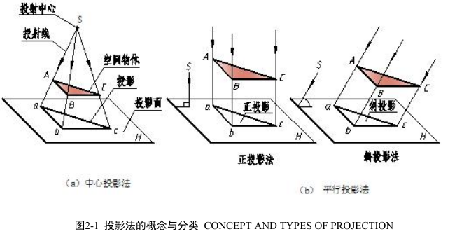
       投影法就是投射线通过物体,向选定的平面投射,并在该平面上获得图形的方法。图 2-1(a)中光源 S 点称为投射中心;SAa、SBb、SCc 称为投射线;平面 H 称为投影面;通过物体上各顶点的投射线与投影面的交点 a、b、c 称为物体上各顶点 A、B、C 在 H投影面上的投影;Δabc 图形即为空间物体 ABC 在 H 投影面上的投影。

      In daily life, when the sunshine or lamplight irradiates an object, there will be a shadow on the ground or the wall. Scientists abstract the natural phenomena to describe an object with projection. The source of light is called the center of projection. Light ray is called projector. The pre-established plane is called projection plane. The graphics on the plane is called projection. In other word,  rojection is when the projection line passes through the object, there will produce projection on the projection plane.

二、投影法的分类 TYPES OF PROJECTION

    (1)中心投影法。投射线汇交于一点的投影法称为中心投影法,如图 2-1(a)所示。

     Central projection: all the projectors meet a point, as shown in fig2-1(a)

    (2)平行投影法。投射线相互平行的投影法称为平行投影法。

     Parallel projection: projectors parallel each other, as shown in fig2-1(b).

      在平行投影法中,根据投射线与投影面的角度不同,又分为两种:正投影法――投射线与投影面相垂直的平行投影法,如图 2-1(b)所示。斜投影法――投射线与投影面相倾斜的平行投影法,如图 2-1(b)所示。

      According to the different angle between projectors and projection plane, parallel projection can be classified orthographic projection and oblique projection. Orthographic projection: if the  projectors are perpendicular to the projection plane, the projection is called orthographic projection, as shown in fig2-1(b).  Oblique projection: if the projectors are oblique to the projection plane, the projection is called oblique projection, as shown in fig2-1(b).

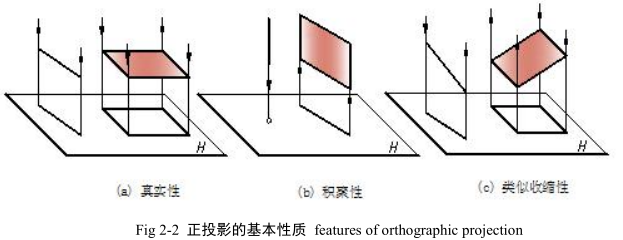
       正投影能真实地表达物体的形状和大小,并且度量性好、作图简便,在工程上应用最广泛。本书主要介绍正投影图。以后各章节中,除特殊说明外,所称投影均指正投影。

       Orthographic projection can show the actual size of object and it is convenient to draw and measure, so it is widely used in engineering drawings. This book introduces the projection drawing. In later chapters, orthographic projection is called projection for short.

       应当指出:投影不同于一般的影子,影子是一片漆黑,只反映物体的外轮廓,而物 体的投影是将围成这个物体的各面、各棱线进行投影。

      It should be pointed out: the projection is different from general shadow, the shadow is a dark, reflect only the outer contour of the object, however, projection can show every plane and line of object.