
建筑详图 Architectural detailed drawing
由于建筑平、立、剖面图一般采用较小的比例绘制,建筑物的某些细部及构配件的详细构造和尺寸无法表示清楚。为了满足施工的要求,必须将这些部位的形状、尺寸、材料、做法等用较大的比例详细表达出来,这种图称为建筑详图,简称详图。详图又称大样图或节点图。
Because the plan, elevation and section drawing of the building are usually drawn in a small scale, the detailed structure and size of some details and components of the building cannot be clearly expressed. In order to meet the requirements of construction, the shape, size, material and method of these parts must be expressed in detail in a larger proportion, which is called the architectural detail map, or the detail map for short. Detail diagram is also known as large sample diagram or node diagram.
建筑详图可分为节点构造详图和构配件详图两类。凡表达房屋某一细部的形状大小、构造做法和材料组成的详图称为节点详图,如墙身详图(包括檐口、窗台、勒脚、明沟、散水等)。凡表明构配件本身构造的详图,称为构件详图或配件详图,如门、窗详图、楼梯详图、花格详图等。
Architectural detail drawings can be divided into two categories: joint construction detail drawings and structural parts detail drawings. The detail drawing expressing the shape, size, construction method and material composition of a certain part of the house is called node detail drawing, such as the detail drawing of the wall body (including cornice, window sill, legging foot, open ditch, water discharge, etc.). Where the details of the construction of the components themselves, known as component details or accessories details, such as door, window details, stairs, lattice details, etc.
建筑详图的数量与房屋的复杂程度及建筑平、立、剖面图的内容及比例有关。对于引用标准图或通用详图的建筑构配件和剖面节点,只要注明所用图集的名称、页次、编号,则可不必再画详图。常用的详图主要有墙身剖面详图、楼梯详图、门窗详图、厨房、浴室、卫生间详图等。
The number of architectural details depends on the complexity of the building and the content and proportions of the plans, elevations and sections. For the construction parts and section nodes that refer to standard drawings or general drawings, it is unnecessary to draw detailed drawings as long as the name, page number and number of the atlas used are indicated. Commonly used details of the main wall body section details, details of stairs, doors and Windows, kitchen, bathroom, toilet and so on.
举例:

图1 楼梯剖面详图
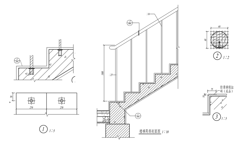
图2 楼梯节点详图

图3 门窗详图

图4 外墙节点详图

