水利工程制图

武心嘉

目录

  • 1 制图基本知识 Basic Knowledge of Drawing
    • 1.1 绪论 Introduction
    • 1.2 制图工具及其用法 Drawing Tools and Their Utilization
    • 1.3 国家标准有关规定 Related Provisions in National Standards
    • 1.4 几何作图geometric construction
    • 1.5 平面图形的绘制 The drawing of plane graphics
  • 2 投影的基础知识 The basics of projection
    • 2.1 投影法和投影特性 Projection method and projection properties
    • 2.2 工程中常用的四种投影图Four kinds of projection drawings commonly used in engineering
    • 2.3 物体的三面投影图 Three-sided projection of an object
  • 3 点线面的正投影 Projection of point、line and plane
    • 3.1 点的投影 Projection of Point
    • 3.2 直线的投影 Projection of Line
    • 3.3 平面的投影 Projection of Plane
    • 3.4 直线与平面、平面与平面的相对位置The position of a line relative to a plane, plane relative to a plane
  • 4 立体 Stereoscopic
    • 4.1 平面体的投影Projection ofProjection of  Planar Solids
    • 4.2 平面立体表面上的点和线 Points and lines on a planar solid surface
    • 4.3 平面立体截交线Plane stereo intersection line
    • 4.4 曲面立体的投影Stereoscopic projection of a curved surface
    • 4.5 曲面立体表面上的点和线Points and lines on the surface of a curved surface
    • 4.6 曲面立体的截交线Curved solid intersection
  • 5 立体表面相交Intersections of solids
    • 5.1 概述Overview
    • 5.2 两平面立体相交Two plane solids intersect
    • 5.3 平面体与曲面体相贯Intersections Between Planar and Curved Solids
    • 5.4 两曲面体的相贯线 The intersecting line of two curved bodies
    • 5.5 常见两曲面立体相贯线的讨论Discussion on the intersecting line of two surfaces
  • 6 组合体 composite solid
    • 6.1 组合体构成分析 Composition analysis
    • 6.2 组合体视图的画法 Composition View
    • 6.3 组合体的尺寸标注 The dimension of the assembly
    • 6.4 组合体视图的阅读 Reading the composite view
  • 7 轴测图的画法  construction of axonometric drawing
    • 7.1 轴测图的基本知识 Basic Knowledge
    • 7.2 平面体的正等测 Isometric Drawing
    • 7.3 平面体的斜二测 Cabinet Drawing
    • 7.4 曲面体的正等测 Isometric Drawing of Curved Solids
    • 7.5 曲面体的斜二测 Cabinet Drawing of Curved Solids
  • 8 工程形体的表达方法Expression methods of engineering objects
    • 8.1 视图 Views
    • 8.2 剖视图 Section View
    • 8.3 断面图 Cross Section
    • 8.4 简化画法和规定画法Simplified and prescriptive drawing
    • 8.5 视图的综合运用 Comprehensive use of views
    • 8.6 补充
  • 9 水工建筑物中常见的曲面 Curved surfaces in water conservancy project
    • 9.1 概述
    • 9.2 椭圆柱和椭圆锥
    • 9.3 双曲抛物面
    • 9.4 组合面Combination of surface
  • 10 标高投影 Projection with heights
    • 10.1 点、直线、平面 Points, lines, planes
    • 10.2 两平面的交线
    • 10.3 曲面和地形面 Curved and topographic surfaces
    • 10.4 标高投影在工程中的应用Application in engineering
  • 11 水利工程图 Hydraulic drawing
    • 11.1 水工建筑物和水工图 Hydraulic structures and drawings
    • 11.2 水利工程图表达 Expression of Hydraulic Engineering Drawing
    • 11.3 水工图的尺寸标注 Dimensioning of hydraulic drawings
    • 11.4 水工图的绘制 Drawing of hydraulic drawings
    • 11.5 水工图的阅读 Reading of hydraulic drawings
  • 12 水利工程制图实训
    • 12.1 题目
  • 13 建筑施工图Building construction drawing
    • 13.1 概述Overview
    • 13.2 建筑总平面图General plan of the building
    • 13.3 建筑平面图Construction plan
    • 13.4 建筑立面图 Elevation of Building
    • 13.5 建筑剖面图Building profile
    • 13.6 建筑详图 Architectural detailed drawing
概述Overview

概述Overview

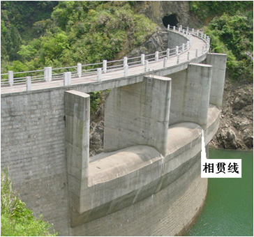
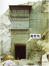
    两立体相交,也称两立体相贯,它们表面的交线称为相贯线。工程形体一般是多种几何形体的组合,当这些基本几何体表面相交时,会产生相贯线。相贯线是几何体表面的分界线。在绘制工程形体的视图时,需要画出相贯线的投影。坝体与闸墩之间、进水口处、两廊道相交处均有相贯线。

       Two solid intersection, also known as two solid intersecting, their surface intersection line known as intersecting line.Engineering bodies are usually a combination of geometric bodies. When these basic surfaces intersect, intersecting lines are generated.Intersecting lines are the boundaries on the surface of geometry.When drawing the view of the engineering body, it is necessary to draw the projection of the intersecting line.There are intersecting lines between dam body and gate pier, water inlet and intersection of two corridors.


      由于立体的形状、大小及相互位置的不同,相贯线的形状也各不相同,可能是直线段或平面曲线段的组合,也可能是空间曲线。但是,所有相贯线都有下列基本性质:    

      1. 相贯线是相交两立体表面的共有线,它的投影必在两立体投影重叠部分的范围以内;

      2. 由于立体有一定的范围,所以相贯线一般是封闭的;

      3. 相贯线是相交立体表面间的分界线,每个参加相交的立体的轮廓线都不能穿过相贯线而进入另一立体内部。

      当一立体全部棱线或素线与另一立体表面相交时称为全贯,全贯时一般有两条相贯线; 当两立体都只有部分棱线或素线与另一立体表面相交时称为互贯,互贯时则只有一条相贯线。

      Due to the different shape, size and position of the solid, the shape of the intersecting line is also different, which may be a combination of a straight line or a plane curve, or a space curve.However, all intersecting lines have the following basic properties:

      1. The intersecting line is the common line of intersecting two stereoscopic surfaces, and its projection must be within the scope of the overlapping part of the two stereoscopic projections;

      2. The intersecting line is generally closed due to a certain stereoscopic range;

      3. Intersecting line is the dividing line between intersecting solid surfaces. The contour line of each intersecting solid cannot cross the intersecting line and enter the interior of another solid.

             求相贯线可分析两立体的相对位置及其相对于投影面的位置;分析相贯线的性质——空间形状及投影情况,选择解题方法。具体步骤如下:


              1. 求相贯线上的控制点及中间点。控制点包括:轮廓线(棱线)上的点,极限位置点——最高最低点、最左最右点、最前最后点,相贯线端点,曲线特征点(如椭圆的长短轴端点、曲线的拐点等);

     2. 根据相贯线的性质依次连接所求各点;

     3. 区别相贯线各段的可见性,并补全立体的投影。

     The relative position of two solids and their position relative to the projection plane can be analyzed by calculating the intersecting line.Analyze the properties of intersecting line - space shape and projection, and choose the method to solve the problem.The specific steps are as follows:

      1. Find the control points and intermediate points of the intersecting line.Control points include: the point on the contour (prism), the limit position point -- the highest and lowest point, the left and right point, the first and last point, the endpoint of the intersecting line, the curve feature point (such as the short and long axis endpoint of the ellipse, the inflection point of the curve, etc.);

      2. Connect the desired points successively according to the property of the intersecting line;

      3. Distinguish the visibility of each segment of the intersecting line, and complete the three-dimensional projection.