
组合体构成分析 Composition analysis
读图的基本依据 Basis of reading
(1)三视图的投影规律。因为画图时每一部分都是按投影规律画出的,所以读图时就应根据投影规律找出每一部分在三视图中的投影范围。
Projection rules: follow the projection rules to make drawings, so one need to find out projection of every line or plane in three views based on the projection rules
(2)基本体三视图的图形特征。熟记基本体三视图的图形特征就能迅速看懂每一部分的形状。
Feature characteristics of basic solids: if one can memorize it , it is easy for him to figure out solids based on three views.
(3)三视图与空间物体的对应关系。掌握三视图与空间物体的对应关系就能判定各部分的相对位置。
The respective correspondence between the three views and solids: To master the relationship can determine the relative position of each part. Feature of three views as to basic solids. Only one memorizes feature of three views about basic solids, can he think out 3d quickly.
2.形体分析读图法 shape analysis
任何工程形体,都是根据它的功能要求,由一些基本形体按一定的组合方式组合而成的。把一个复杂形体分解成若干简单形体,并分析这些简单形体的形状、相对位置、组合方式、交线情祝,形成对整个组合体的完整概念,从而进行画图、读图和标注尺寸的思维方法,称为形体分析法。这种分析方法是画图、读图、尺寸标注及构形设计中常采用的分析法。形体分析读图法的要点就是一部分一部分地看,具体读图步骤可分为:
Any engineering form is composed of some basic forms according to its functional requirements To work out.Decompose a complex body into several simple bodies, and analyze the shapes, relative positions, Form a complete concept of the whole assembly, so as to draw, read and mark the ruler Inch's way of thinking is called body analysis.This analysis method is drawing, reading, dimension and configuration design The usual analysis method.The key points of shape analysis are to divide views into several parts and find out projection in the three views of each part. Produce the solid of each part based on projection and assemble every solid. The reading steps are as following. Shape analysis method is to divide the solid into several parts and imagine the shape of every part and analyze their relative position and assembly the overall shape.
(1)识视图、分部分。识视图即是弄清各视图的观看方向,各视图与空间物体之间的方位关系,从而建立起图物关系,这是整个看图过程中所不能忽视的问题;分部分应从一个投影重叠较少,结构关系明显的视图入手,结合其它视图,按线框把视图分解为若干部分。
Analyze views and divide frames: firstly, one should make sure the projection direction of each view and relative position between views and solids. Secondly, one also needs to determine a view to divide and the view must make it easy to depart. Finally, divide the view into several wireframes considering the other two views at the same time.
(2)逐部分对投影、想形状。根据投影规律,逐一找出每个线框在其它视图中的对应投影,然后根据基本体三视图的图形特征,逐一想象出空间形状。
Find out projection and imagine solid of each part:According to the projection rule, find out every wire frame corresponding projection in the other two views, and then produce the basic solid based on projection feature one by one.
(3)综合起来想整体。判断出各部分的形状之后,按它们的相互位置,综合想象出整体形状。
Assemble the whole solid. Combine each basic solid and assemble a simple solid.
叠加体
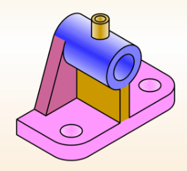
把几个基本形体按一定的相对位置叠放在一起,构成组合体的方法,在其结合处往在产生一些分界线。根据叠加形体表面的相对位置关系,可分为如下几种情况:共面两个形体表面共面(平面与平面),在两表面之间无分界线。如轴承台的套筒与加强肋板、加强肋板与底板的前端面相切两个形体表面(平面与曲面或曲面与曲面)相切,其结合处呈光滑过渡,不存在分界线。如轴承台的套筒与支承板。相交两个形体表面相交时,在结
合处将产生交线。如轴承台的小圆筒与套筒的相贯线、套筒与支承板的截交线、加强肋板与底板的分界线。
【例 6-1】识读图 6-1(a)所示三视图,想象出该物体的立体形状。
Please imagine the simple solid based on the given views.
分析 analyze
① 识视图、分部分。先识视图后分部分,看主视图有三个线框,对应左视图各线框都是凸出来的部分,可知该物体是由三个基本体叠加形成,如图6-1(a)所示。
Analyze views and divide wireframes. Divide the front view into three wireframes and judge the simple solid is made of three basic solids as shown in fig 2-1(a).
② 逐部分对投影、想形状。先看主视图第“1”部分矩形线框,根据投影规律对应俯视图和左视图,该部分的投影都是矩形线框,由基本体三视图图形特征可判定该部分形体是长方体;同理分析第“2”部分组合线框,对应两个矩形线框,形体为组合柱;看第“3”部分三角形线框,对应两个矩形线框,形体为三棱柱,如图6-1(b)所示。
Find out projection of each part and imagine basic solids. The front view of part is a rectangle and the other two views are both rectangles based on projection rules.According to projection characteristics of basic solid, the basic solid of part 1 is a box. the solid of part 2 is a composite column because its front view is a composite frame and the other two views are both rectangles; the solid of part 3 is a triangular prism in the same way.
③ 综合起来想整体。由主视图可看出,组合柱和三棱柱均在长方体之上,并左右居中;由左视图可看出,组合柱在后,三棱柱在前,组合柱与长方体后边靠齐,整体形状如图 6-1(c)所示。
Combination the overall simple solid based on relative positions among the three basic solids. From the front view can be seen that the composite column and the prism on the top of the box and locate in the middle; from left view can be seen that column in back and prism in front, composite column and the box alignment in back. The overall shape is as shown in Figure 6-1 (c).
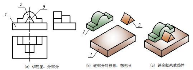
图 6-1 叠加式简单体三视图的识读示例 Reading sample of superposition solid
切割与穿孔
当形体被平面或曲面切割时,在形体表面产生各种形状的交线。右图所示的长方体被平面和圆柱面切掉两个角和中间一个半圆柱后,形成的交线分别为直线和圆弧。
【例 6-2】识读图 6-2(a)所示三视图,想象出该物体的立体形状。
Please make the solid in space based on the given views.
分析 analyze
① 识视图、分部分。先识视图后分部分,看三个视图中的小线框都套在大线框内,可以判定该物体是由基本体切割形成,分部分时,应先把原体分为一部分,然后再分切割处。各视图中大线框就是原体的投影,分为第“1”部分,另有两处切割,共分三部分,如图 6-2(a)所示。
② 逐部分对投影、想形状;综合起来成整体。先看第“1”部分原体,三视图均为矩形是长方体,如图6-2(b)所示;看第“2”部分,三角形线框对应两个两矩形线框,即在原体的左上前角切去了一个三棱柱,如图 6-2(c)所示;看第“3”部分,U 形线框对应两个矩形线框,即在原体的右边上下正中挖了一个 U 形通槽,综合起来即为整体,如图 6-2(d)所示。
Analyze the given views and divide the front view into three wireframe. Because the wireframe of part 1 includes part 2 and part 3, one can regard the simple solid is a cutting solid. The original solid is a box then subtract two basic solids.Find out projections of three parts and imagine solid one by one. Part 1 is a box, part 2 is a triangular prism, and then, the part 3 is a composite column respectively. Combine the overall cutting solid. The procedure of producing solid is as following.
Step1. work out an original solid as to the known views.As for the example, one can regard it as a box based on the three rectangles.
Step2. cut a triangular prism away based on the front view.
Step3. cut a composite column away based on the front view.
Step4. check the solution and the three views.
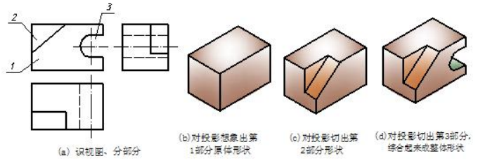
图6-2 切割式简单体三视图的识读示例 Fig 6-2 reading sample of cutting solid

