水利工程制图

武心嘉

目录

  • 1 制图基本知识 Basic Knowledge of Drawing
    • 1.1 绪论 Introduction
    • 1.2 制图工具及其用法 Drawing Tools and Their Utilization
    • 1.3 国家标准有关规定 Related Provisions in National Standards
    • 1.4 几何作图geometric construction
    • 1.5 平面图形的绘制 The drawing of plane graphics
  • 2 投影的基础知识 The basics of projection
    • 2.1 投影法和投影特性 Projection method and projection properties
    • 2.2 工程中常用的四种投影图Four kinds of projection drawings commonly used in engineering
    • 2.3 物体的三面投影图 Three-sided projection of an object
  • 3 点线面的正投影 Projection of point、line and plane
    • 3.1 点的投影 Projection of Point
    • 3.2 直线的投影 Projection of Line
    • 3.3 平面的投影 Projection of Plane
    • 3.4 直线与平面、平面与平面的相对位置The position of a line relative to a plane, plane relative to a plane
  • 4 立体 Stereoscopic
    • 4.1 平面体的投影Projection ofProjection of  Planar Solids
    • 4.2 平面立体表面上的点和线 Points and lines on a planar solid surface
    • 4.3 平面立体截交线Plane stereo intersection line
    • 4.4 曲面立体的投影Stereoscopic projection of a curved surface
    • 4.5 曲面立体表面上的点和线Points and lines on the surface of a curved surface
    • 4.6 曲面立体的截交线Curved solid intersection
  • 5 立体表面相交Intersections of solids
    • 5.1 概述Overview
    • 5.2 两平面立体相交Two plane solids intersect
    • 5.3 平面体与曲面体相贯Intersections Between Planar and Curved Solids
    • 5.4 两曲面体的相贯线 The intersecting line of two curved bodies
    • 5.5 常见两曲面立体相贯线的讨论Discussion on the intersecting line of two surfaces
  • 6 组合体 composite solid
    • 6.1 组合体构成分析 Composition analysis
    • 6.2 组合体视图的画法 Composition View
    • 6.3 组合体的尺寸标注 The dimension of the assembly
    • 6.4 组合体视图的阅读 Reading the composite view
  • 7 轴测图的画法  construction of axonometric drawing
    • 7.1 轴测图的基本知识 Basic Knowledge
    • 7.2 平面体的正等测 Isometric Drawing
    • 7.3 平面体的斜二测 Cabinet Drawing
    • 7.4 曲面体的正等测 Isometric Drawing of Curved Solids
    • 7.5 曲面体的斜二测 Cabinet Drawing of Curved Solids
  • 8 工程形体的表达方法Expression methods of engineering objects
    • 8.1 视图 Views
    • 8.2 剖视图 Section View
    • 8.3 断面图 Cross Section
    • 8.4 简化画法和规定画法Simplified and prescriptive drawing
    • 8.5 视图的综合运用 Comprehensive use of views
    • 8.6 补充
  • 9 水工建筑物中常见的曲面 Curved surfaces in water conservancy project
    • 9.1 概述
    • 9.2 椭圆柱和椭圆锥
    • 9.3 双曲抛物面
    • 9.4 组合面Combination of surface
  • 10 标高投影 Projection with heights
    • 10.1 点、直线、平面 Points, lines, planes
    • 10.2 两平面的交线
    • 10.3 曲面和地形面 Curved and topographic surfaces
    • 10.4 标高投影在工程中的应用Application in engineering
  • 11 水利工程图 Hydraulic drawing
    • 11.1 水工建筑物和水工图 Hydraulic structures and drawings
    • 11.2 水利工程图表达 Expression of Hydraulic Engineering Drawing
    • 11.3 水工图的尺寸标注 Dimensioning of hydraulic drawings
    • 11.4 水工图的绘制 Drawing of hydraulic drawings
    • 11.5 水工图的阅读 Reading of hydraulic drawings
  • 12 水利工程制图实训
    • 12.1 题目
  • 13 建筑施工图Building construction drawing
    • 13.1 概述Overview
    • 13.2 建筑总平面图General plan of the building
    • 13.3 建筑平面图Construction plan
    • 13.4 建筑立面图 Elevation of Building
    • 13.5 建筑剖面图Building profile
    • 13.6 建筑详图 Architectural detailed drawing
断面图 Cross Section

断面图 Cross section

1、概念 Concept      

     假想用一个平面把物体切开,仅画出剖切到的切口图形,并且画上相应的材料图例,所得到的图形称为断面图。If an object is cut with an imaginary plane and only the cut graph is drawn and the corresponding material legend is drawn, the graph obtained is called section drawing.

2、与剖视图的区别 The difference with the sectional view

     剖视图 —— 要画出剖切平面后沿投影方向能看到的所有部分的投影

     Section view - to draw the projection of all the parts that can be seen in the projection direction after cutting the plane

     断面图 —— 仅画出剖切平面与物体接触部分的图形,即切口实形。

3、断面图分类 Sorts of cross section

      断面图主要根据不同的安排分为移出断面图和中断断面图。

      The sections can be divided into removed  and revolved cross section based on the different arrangement of the section.

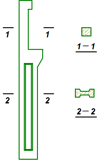
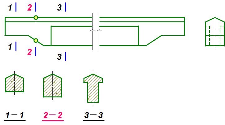
(1)移出断面图Removed cross section

        绘在基本视图之外的断面图称为移出断面图,应用于断面变化比较多的构件。

      The section drawn outside the basic view is called the removal section and is applied to the component with more changes in section.

       绘制方法 Construction methods

       断面图的绘制方法与剖视图一样,但只需画出剖切平面与物体接触部分的图形,即切口实形。

       Same as section but don’t need to draw some visible outside just want to draw solid parts touching the cutting plane.

       符号 Label

       断面图的剖切符号只画出剖切位置线,不画投射方向线,而是用编号的注写位置来表示剖切后的投射方向。剖面图中的剖切平面可转折,断面图中的剖切平面则不能转折。

       In the section cut sign of section cut, only the cutting position line is drawn, and the projection direction line is not drawn. Instead, the numbered annotation position is used to represent the projection direction after cutting.The cutting plane in the section can be turned, but the cutting plane in the section can't be turned.

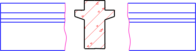
(2)中断断面图 Revolved cross section

       直接画在杆件中断处的断面图,称为中断断面图。多用于杆件细长,且只有单一断面的构件。无需注写断面符号。

      The section drawing drawn directly on the middle of the member is called the interrupt section drawing.It is used for long and thin member with single section.No cross section notation is required.

4、断面图的读图步骤 Reading of cross sections

       Reading steps are as follows.

Step1 understand the solid of given views.

Step2 know the representations of given views.

Step3 make sure the location of sectional views or cross section cutting location.

Step4 draw sectional views or cross section.

Step5 remember to draw sectioning line.

Tips: it is important to dimension the location and projection direction of sectional views.