水工建筑物和水工图 Hydraulic structures and drawings
表达水利工程建筑物设计意图、施工过程的图样称为水利工程图,简称水工图。
The drawings expressing the design intention and construction process of water conservancy engineering buildings are called water conservancy engineering drawings, or hydraulic drawings for short.
水利工程各个阶段对图样均有不同的要求,勘察阶段有地形图、工程地质图;设计阶段有枢纽布置图、建筑物结构图、细部构造图;施工阶段有施工图;验收阶段有竣工图等。
Each stage of the water conservancy project has different requirements for the drawing, the survey stage has topographic map, engineering geological map; In the design stage, there are hub layout, building structure drawing and detail structure drawing. Construction drawings are available at the construction stage; The acceptance stage has the as-built drawing and so on.
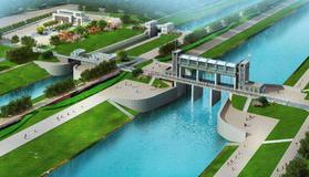
一、工程规划图Engineering plan
主要表示水利枢纽所在的地理位置,与枢纽有关的河流、公路、铁路、重要的建筑物和居民区。
It mainly refers to the geographical location of the water conservancy project, rivers, roads, railways, important buildings and residential areas related to the project.
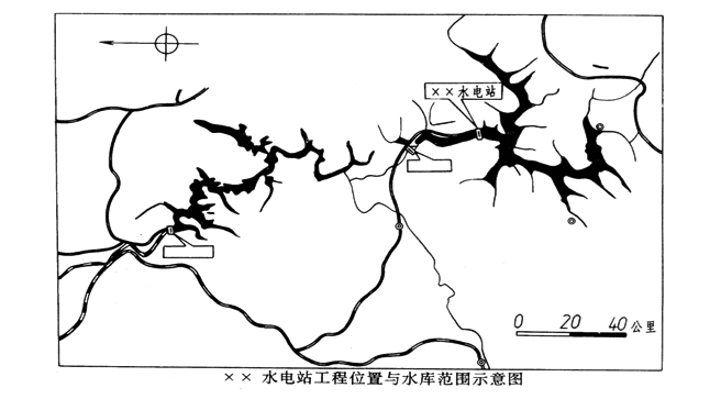
图11-1 工程规划图Engineering plan
二、枢纽布置图 terminal layout
主要表示整个水利枢纽在平面和立面的布置情况。
It mainly represents the layout of the whole water conservancy project in plane and elevation.
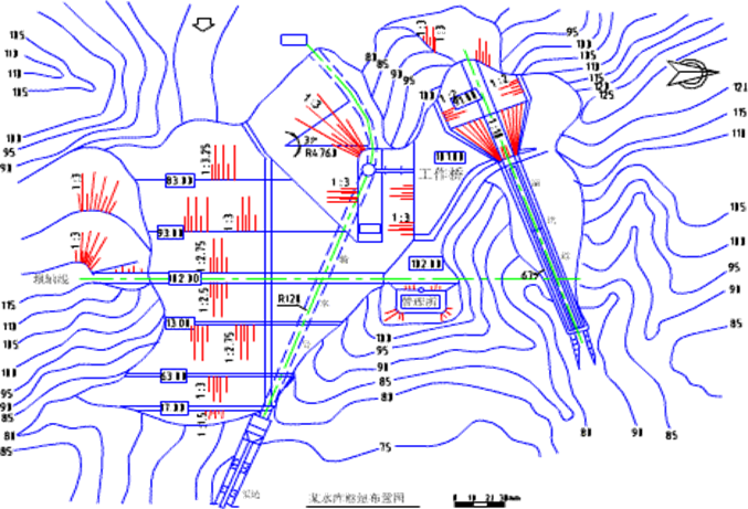
图11-2 枢纽布置图 terminal layout
三、建筑物结构图 Building plan
表示水利枢纽或渠系中某一建筑物为对象的工程图样。
An engineering drawing representing a building in a water conservancy project or canal system.
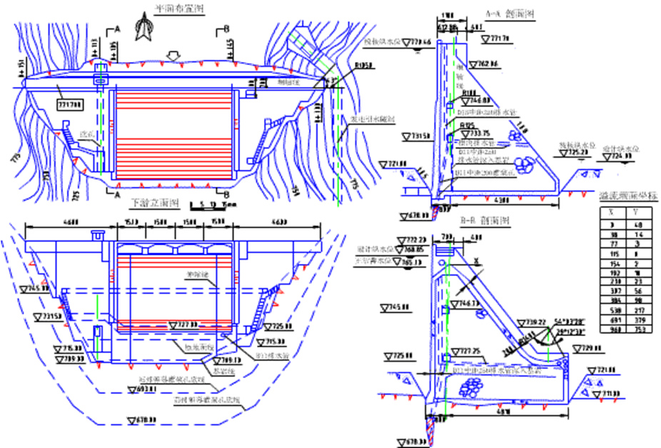
图11-3 建筑物结构图 Building plan
四、施工图 construction drawing
表示水利工程施工组织和施工方法等的图样。
A drawing showing the construction organization and methods of a water conservancy project.
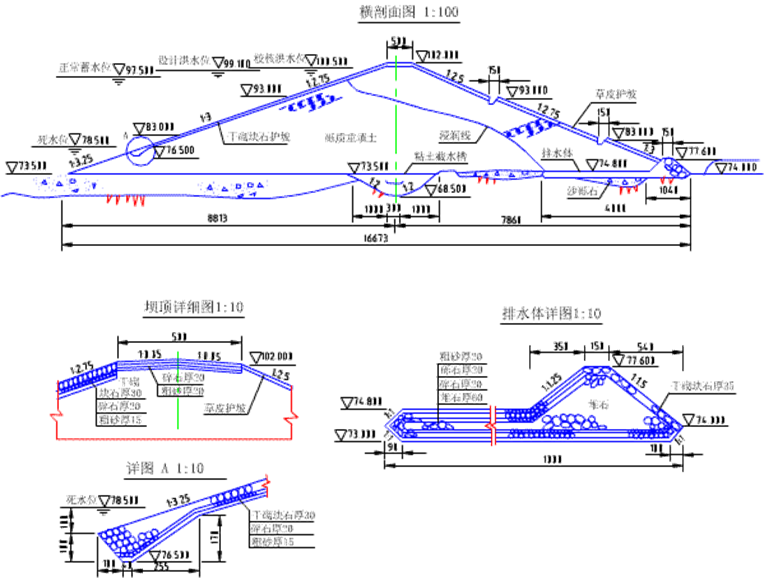
图11-4 施工图 construction drawing
五、竣工图 as-built drawing
按竣工后建筑物的实际结构绘制竣工图,供存档和工程管理用。
Draw the as-built drawing according to the actual structure of the building after completion for archiving and project.

