水工图的尺寸标注 Dimensioning of hydraulic drawings
一、高度尺寸的注法 Height dimension injection method
水工建筑物的高度,除了注写垂直方向的尺寸外,一些重要的部位,如建筑物的顶面、底面、水位等均须标注高程,即标高。常在建筑物立面图和垂直方向的剖视图、断面图中标注。
In addition to the vertical dimension, the elevation of some important parts, such as the top, bottom and water level of the building, shall be marked, that is, the elevation. It is often marked in the building elevation drawing and the vertical direction section view, section view.
(1)标高包括标高符号及尺寸数字两部分。标高符号一般采用等腰直角三角形,用细实线绘制,其高度h约为数字高度的2/3,如图11-12(a)所示。标高符号尖端可以向下指,也可以向上指,根据需要而定,但必须与被标注高度的轮廓线或引出线接触。
(1) elevation includes two parts: elevation symbol and dimension number. The elevation symbol is usually an isosceles right triangle, drawn with a fine solid line, whose height h is about 2/3 of the digital height, as shown in FIG. 11-12 (a). The tip of the elevation symbol may point downward or upward, as required, but must be in contact with the contour or exit line of the marked height.
水面标高(简称水位),水面线以下画三条渐短细实线,如图11-12(c)所示。标高数字一律注写在标高符号右边,单位以米计,注写到小数点后第三位。在总布置图中,可注写到小数点后第二位。零点标高注成±0.000,正数标高数字前一律不加“+”号,负数标高数字前必须加注“-”号,如-1.500。
Water level (hereinafter referred to as water level), three tapering fine solid lines are drawn below the water surface line, as shown in FIG. 11-12 (c). Elevation figures are marked to the right of the elevation mark, in meters, and to the third decimal place. In the general layout, it may be noted to the second decimal place. Zero elevation shall be injected as ±0.000, positive elevation shall not be preceded by "+" sign, negative elevation shall be preceded by "-" sign, such as -1.500.
(2)在平面图中,高程符号为细实线矩形线框,矩形线框的长、宽比约为2:1,在其内注写标高数字,其形式如图11-12(b)所示。
(2) in the plane plan, the height symbol is the rectangular frame with fine solid lines, and the ratio of length and width of the rectangular frame is about 2:1, in which the elevation number is written, as shown in FIG. 11-12 (b).
(3)高程基准与测量基准一致,高度尺寸的基准可采用主要设计高程为基准,或按施工要求选取,一般采用建筑物的底面为基准,仍采用标注高度的方法标注。如图11-12(d)、(e)所示。
(3) the elevation datum is consistent with the measurement datum. The datum of height size can adopt the main design elevation as the datum, or choose according to the construction requirements. Generally, the underside of the building is used as the datum, and the method of marking height is still adopted. See fig.11-12 (d) and (e).
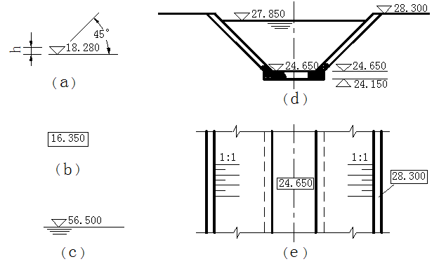
图11-12 标高注法
二、平面尺寸的注法 Injection method of plane size
水工建筑物建造在地面上,通常是根据测量坐标系来确定各个建筑物在地面上的位置。这里主要介绍平面布置图中的尺寸基准。
Hydraulic structures are built on the ground, usually according to the measurement coordinate system to determine the location of each building on the ground. Here mainly introduces the size reference in the layout plan.
水利枢纽中各个水工建筑物在地面上的位置是以所选定的基准点或基准线进行放样定位的,基准点的平面位置是根据测量坐标来确定的,两个基准点相连即确定了基准线的平面位置。如图11-13所示的平面布置图中,坝轴线的位置是由坝端两个基准点的测量坐标来确定的,坝轴线的走向用方位角表示。
The location of each hydraulic structure on the ground in a water conservancy project is based on the selected datum point or datum line for lofting positioning. The plane position of the datum point is determined according to the measured coordinate. The plane position of the datum line is determined when the two datum points are connected. In the layout plan shown in FIG. 11-13, the position of the dam axis is determined by the measurement coordinates of the two reference points at the end of the dam, and the direction of the dam axis is expressed by the azimuth Angle.
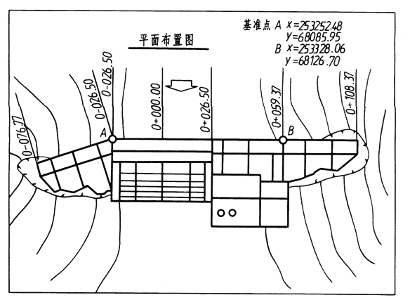
图11-13 平面布置图
建筑物在长度或宽度方向若为对称形状,则以对称轴线为尺寸基准。如图11-14所示,进水闸平面图的宽度尺寸就是以对称轴线为基准的。若建筑物某一方向无对称轴线时,则以建筑物的主要结构端面为基准,如图8-35所示进水闸的长度尺寸则以闸室溢流底槛上游端面为基准之一。
If the building is symmetrical in length or width, the symmetrical axis shall be used as the dimension reference. As shown in figure 11-14, the width and dimension of the plan of the inlet gate are based on the symmetrical axis. If there is no symmetrical axis in a certain direction of the building, the main structural end face of the building shall be taken as the reference. As shown in FIG. 11-14, the length and size of the entry gate shall take the upper end face of overflow bottom sill as one of the reference.
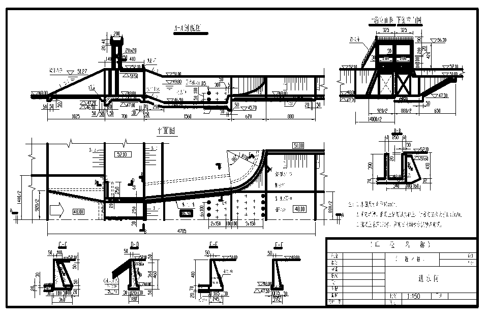
图11-14 进水闸设计图
三、桩号的注法 Injection method of pile number
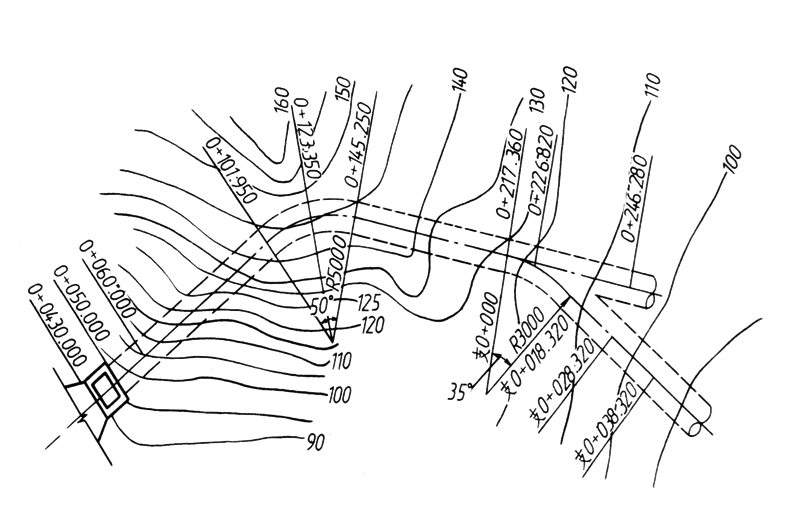
对于坝、隧洞、渠道等较长的水工建筑物,沿轴线的长度尺寸一般采用“桩号”的注法,标注形式为k+m,k为公里数,m为米数。
For long hydraulic structures such as DAMS, tunnels and channels, "pile number" method is generally adopted for the length and size along the axis, and the marked form is k+m, k is the number of kilometers, and m is the number of meters.
如下图所示。起点桩号标注成0+000,起点桩号之后,k、m为正值,起点桩号之前,k、m为负值。桩号数字一般沿垂直于轴线的方向注写,且标注在同一侧。当同一图中几种建筑物均采用“桩号”标注时,可在桩号数字之前加注文字以示区别,如坝0+021.00,洞0+018.30等。
This is shown below. Starting point pile number is marked as 0+000. After starting point pile number, k and m are positive values; before starting point pile number, k and m are negative values. The number of pile number is usually written along the direction perpendicular to the axis and marked on the same side. When several buildings in the same figure are marked with "pile number", words can be added before the number of pile to show the difference, such as dam 0+021.00, hole 0+018.30, etc.
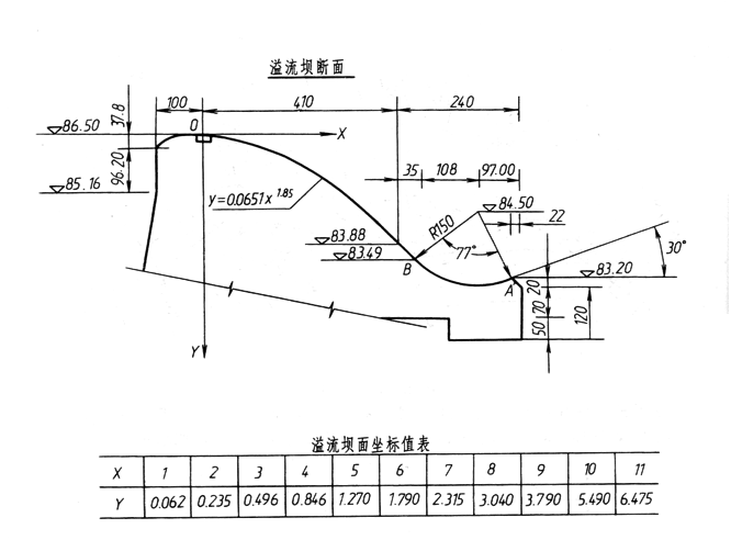
四、非圆曲线的尺寸注法 Dimension injection method for non - circular curves