水利工程制图

武心嘉

目录

  • 1 制图基本知识 Basic Knowledge of Drawing
    • 1.1 绪论 Introduction
    • 1.2 制图工具及其用法 Drawing Tools and Their Utilization
    • 1.3 国家标准有关规定 Related Provisions in National Standards
    • 1.4 几何作图geometric construction
    • 1.5 平面图形的绘制 The drawing of plane graphics
  • 2 投影的基础知识 The basics of projection
    • 2.1 投影法和投影特性 Projection method and projection properties
    • 2.2 工程中常用的四种投影图Four kinds of projection drawings commonly used in engineering
    • 2.3 物体的三面投影图 Three-sided projection of an object
  • 3 点线面的正投影 Projection of point、line and plane
    • 3.1 点的投影 Projection of Point
    • 3.2 直线的投影 Projection of Line
    • 3.3 平面的投影 Projection of Plane
    • 3.4 直线与平面、平面与平面的相对位置The position of a line relative to a plane, plane relative to a plane
  • 4 立体 Stereoscopic
    • 4.1 平面体的投影Projection ofProjection of  Planar Solids
    • 4.2 平面立体表面上的点和线 Points and lines on a planar solid surface
    • 4.3 平面立体截交线Plane stereo intersection line
    • 4.4 曲面立体的投影Stereoscopic projection of a curved surface
    • 4.5 曲面立体表面上的点和线Points and lines on the surface of a curved surface
    • 4.6 曲面立体的截交线Curved solid intersection
  • 5 立体表面相交Intersections of solids
    • 5.1 概述Overview
    • 5.2 两平面立体相交Two plane solids intersect
    • 5.3 平面体与曲面体相贯Intersections Between Planar and Curved Solids
    • 5.4 两曲面体的相贯线 The intersecting line of two curved bodies
    • 5.5 常见两曲面立体相贯线的讨论Discussion on the intersecting line of two surfaces
  • 6 组合体 composite solid
    • 6.1 组合体构成分析 Composition analysis
    • 6.2 组合体视图的画法 Composition View
    • 6.3 组合体的尺寸标注 The dimension of the assembly
    • 6.4 组合体视图的阅读 Reading the composite view
  • 7 轴测图的画法  construction of axonometric drawing
    • 7.1 轴测图的基本知识 Basic Knowledge
    • 7.2 平面体的正等测 Isometric Drawing
    • 7.3 平面体的斜二测 Cabinet Drawing
    • 7.4 曲面体的正等测 Isometric Drawing of Curved Solids
    • 7.5 曲面体的斜二测 Cabinet Drawing of Curved Solids
  • 8 工程形体的表达方法Expression methods of engineering objects
    • 8.1 视图 Views
    • 8.2 剖视图 Section View
    • 8.3 断面图 Cross Section
    • 8.4 简化画法和规定画法Simplified and prescriptive drawing
    • 8.5 视图的综合运用 Comprehensive use of views
    • 8.6 补充
  • 9 水工建筑物中常见的曲面 Curved surfaces in water conservancy project
    • 9.1 概述
    • 9.2 椭圆柱和椭圆锥
    • 9.3 双曲抛物面
    • 9.4 组合面Combination of surface
  • 10 标高投影 Projection with heights
    • 10.1 点、直线、平面 Points, lines, planes
    • 10.2 两平面的交线
    • 10.3 曲面和地形面 Curved and topographic surfaces
    • 10.4 标高投影在工程中的应用Application in engineering
  • 11 水利工程图 Hydraulic drawing
    • 11.1 水工建筑物和水工图 Hydraulic structures and drawings
    • 11.2 水利工程图表达 Expression of Hydraulic Engineering Drawing
    • 11.3 水工图的尺寸标注 Dimensioning of hydraulic drawings
    • 11.4 水工图的绘制 Drawing of hydraulic drawings
    • 11.5 水工图的阅读 Reading of hydraulic drawings
  • 12 水利工程制图实训
    • 12.1 题目
  • 13 建筑施工图Building construction drawing
    • 13.1 概述Overview
    • 13.2 建筑总平面图General plan of the building
    • 13.3 建筑平面图Construction plan
    • 13.4 建筑立面图 Elevation of Building
    • 13.5 建筑剖面图Building profile
    • 13.6 建筑详图 Architectural detailed drawing
组合体视图的阅读 Reading the composite view

组合体的阅读 Group reading

(1)刻模型。刻模型的方法适用于初学者,其要点是:利用已知视图的外轮廓先想出大致表示一个什么基本形体,而后利用每个视图的观看方向,边看图边刻模型,直至模型与视图完全对应。

Make models. The way is good for a beginner. The thinking is like that: first, imagine a basic solid based on the given views, and then , cut it based on the details of each view until the three views of the model are same as the given views.

【例 6-5】识读图 6-6(a)所示三视图,刻出该物体的模型。Make model based on given views.

分析 analyze

① 先刻出原体模型。看物体三视图小线框均在大线框内,可以判定该物体是由基本体切割而成的,原体可视为长方体,如图 6-6(b)所示。

Make the original model. One can guess it a box based on given views and as shown in fig 2-6(b).

② 逐步刻出模型的切割处。看左视图在长方体前上方斜切一刀,如图6-6 (c)所示;看主视图在长方体上方左右角各斜切一刀,如图 6-6 (d)所示;看俯视图在前方正中切三刀挖一个槽,如图 6-6 (e)所示。

Cut it and get the required model. First cut a triangular prism away from the left view; subtract two triangular pyramids from the front view; cut a box away from the top view as shown in fig2-6 (e).

③ 将所刻模型与三视图反复对照,直至模型正确。

Compare the model with the three views until the model is correct.

(2)根据两面视图补画第三视图。该练习简称“补视图”或“二补三”,这是一种最常用的练习读图的方

法,它不仅练习读图,同时也练习画图。

Complete the missing view based on given views. It is widely used in training reading and drawing.


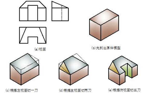
                                          图6-6 读图刻模型示例 Fig 6-6 sample of making model

【例 6-6】识读图 6-7(a)所示两面视图,想象出该物体的空间形状并补出第三视图。

       Imagine the solid and complete the missing view based on the given views. Provide the solid based on the given two views and come up with solid and complete the third view. 

分析 analyze 

      Take the two views into account and determine to divide three frames in the front view.Follow the principle of projection rule to find out projection in the top view of the three frames in every case.Think out the shape one by one and assembly(组装) the whole shape.

      补视图前应首先根据已给的两面视图,按照前面所述的读图方法想象出物体的立体形状。该物体由两个长方体和一个 U 型柱三部分叠加,叠加后在前后方向又挖一个圆柱通孔,形状如图 6-7(b)所示。根据投影规律,按照前面所述的画图思路,补出第三视图,作图步骤如图 6-7(c)所示。

Step1. Divide the front view into three parts and imagine basic solid one by one based on the basis of reading.

Step2. Combine the superposition solid based on the relative positions among the three basic solids.

Step 3. Complete view of each basic solid and check the solution.


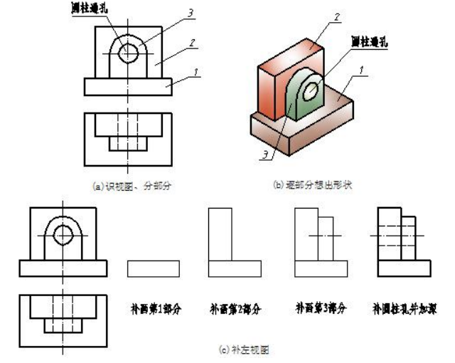
                                      图6-7 补视图示例 fig 6-7 sample of complete missing view