水利工程制图

武心嘉

目录

  • 1 制图基本知识 Basic Knowledge of Drawing
    • 1.1 绪论 Introduction
    • 1.2 制图工具及其用法 Drawing Tools and Their Utilization
    • 1.3 国家标准有关规定 Related Provisions in National Standards
    • 1.4 几何作图geometric construction
    • 1.5 平面图形的绘制 The drawing of plane graphics
  • 2 投影的基础知识 The basics of projection
    • 2.1 投影法和投影特性 Projection method and projection properties
    • 2.2 工程中常用的四种投影图Four kinds of projection drawings commonly used in engineering
    • 2.3 物体的三面投影图 Three-sided projection of an object
  • 3 点线面的正投影 Projection of point、line and plane
    • 3.1 点的投影 Projection of Point
    • 3.2 直线的投影 Projection of Line
    • 3.3 平面的投影 Projection of Plane
    • 3.4 直线与平面、平面与平面的相对位置The position of a line relative to a plane, plane relative to a plane
  • 4 立体 Stereoscopic
    • 4.1 平面体的投影Projection ofProjection of  Planar Solids
    • 4.2 平面立体表面上的点和线 Points and lines on a planar solid surface
    • 4.3 平面立体截交线Plane stereo intersection line
    • 4.4 曲面立体的投影Stereoscopic projection of a curved surface
    • 4.5 曲面立体表面上的点和线Points and lines on the surface of a curved surface
    • 4.6 曲面立体的截交线Curved solid intersection
  • 5 立体表面相交Intersections of solids
    • 5.1 概述Overview
    • 5.2 两平面立体相交Two plane solids intersect
    • 5.3 平面体与曲面体相贯Intersections Between Planar and Curved Solids
    • 5.4 两曲面体的相贯线 The intersecting line of two curved bodies
    • 5.5 常见两曲面立体相贯线的讨论Discussion on the intersecting line of two surfaces
  • 6 组合体 composite solid
    • 6.1 组合体构成分析 Composition analysis
    • 6.2 组合体视图的画法 Composition View
    • 6.3 组合体的尺寸标注 The dimension of the assembly
    • 6.4 组合体视图的阅读 Reading the composite view
  • 7 轴测图的画法  construction of axonometric drawing
    • 7.1 轴测图的基本知识 Basic Knowledge
    • 7.2 平面体的正等测 Isometric Drawing
    • 7.3 平面体的斜二测 Cabinet Drawing
    • 7.4 曲面体的正等测 Isometric Drawing of Curved Solids
    • 7.5 曲面体的斜二测 Cabinet Drawing of Curved Solids
  • 8 工程形体的表达方法Expression methods of engineering objects
    • 8.1 视图 Views
    • 8.2 剖视图 Section View
    • 8.3 断面图 Cross Section
    • 8.4 简化画法和规定画法Simplified and prescriptive drawing
    • 8.5 视图的综合运用 Comprehensive use of views
    • 8.6 补充
  • 9 水工建筑物中常见的曲面 Curved surfaces in water conservancy project
    • 9.1 概述
    • 9.2 椭圆柱和椭圆锥
    • 9.3 双曲抛物面
    • 9.4 组合面Combination of surface
  • 10 标高投影 Projection with heights
    • 10.1 点、直线、平面 Points, lines, planes
    • 10.2 两平面的交线
    • 10.3 曲面和地形面 Curved and topographic surfaces
    • 10.4 标高投影在工程中的应用Application in engineering
  • 11 水利工程图 Hydraulic drawing
    • 11.1 水工建筑物和水工图 Hydraulic structures and drawings
    • 11.2 水利工程图表达 Expression of Hydraulic Engineering Drawing
    • 11.3 水工图的尺寸标注 Dimensioning of hydraulic drawings
    • 11.4 水工图的绘制 Drawing of hydraulic drawings
    • 11.5 水工图的阅读 Reading of hydraulic drawings
  • 12 水利工程制图实训
    • 12.1 题目
  • 13 建筑施工图Building construction drawing
    • 13.1 概述Overview
    • 13.2 建筑总平面图General plan of the building
    • 13.3 建筑平面图Construction plan
    • 13.4 建筑立面图 Elevation of Building
    • 13.5 建筑剖面图Building profile
    • 13.6 建筑详图 Architectural detailed drawing
点、直线、平面 Points, lines, planes

点、直线、平面 Points, lines, planes

一、点的标高投影    Elevation projection of point

      基准面以上的高程为正(可省略+),基准面以下的高程为负(-),单位为米。为了表示几何元素间的距离或线段的长度,标高投影中要附以比例尺。用比例尺丈量,即可知A、B、C任意两点间的实际水平距离。见图10-2。

      Elevation above the base level is positive (+ can be omitted), elevation below the base level is negative (-), and the unit is meters. To indicate the distance between geometric elements or the length of a line segment, a scale is attached to the elevation projection. The actual horizontal distance between any two points of A, B and C can be known by measuring with A scale.

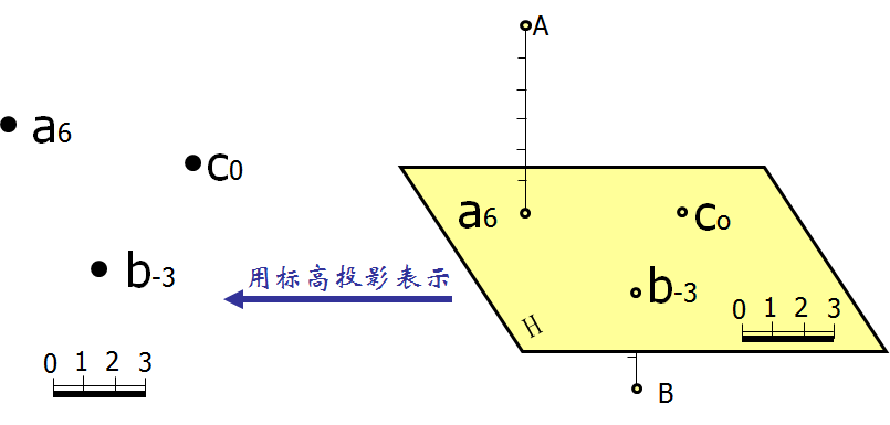
图10-2 点的标高投影    Elevation projection of point

二、直线的标高投影  Elevation projection of lines

1、直线的水平投影及线上两点的高程,如图10-3。

The horizontal projection of a line and the elevation of two points on the line.
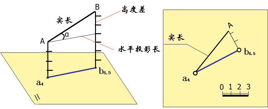
图10-3  直线的水平投影(1)

2、直线的方向及线上一点的高程,如图10-4。

The direction of a line and the elevation of a point on it.
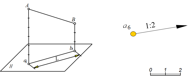
图10-4  直线的水平投影(2)

 坡度 Slope —— 直线上任意两点的高差和水平距离之比,用 i 表示。

 平距 Horizontal Distance —— 直线上两点的高差为1个单位时两点的水平距离,用 l 表示。
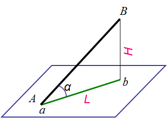
图10-5 坡度与平距

三、平面的标高投影 Elevation projection of planes

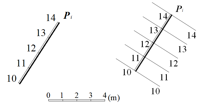
      平面内的水平线就是等高线,可看作水平面与该平面的交线。 平面上的等高线的特性:等高线是直线;等高线互相平行,其投影也互相平行;等高线的高差相等时,其水平间距也相等。如图10-6(a)。

      The horizontal line in the plane is the contour line, which can be regarded as the intersection of the horizontal plane and the plane. Characteristics of contour lines in plane: contour lines are straight lines; The contour lines are parallel to each other and the projections are parallel to each other. When the height difference of contour lines is equal, the horizontal spacing is also equal.


(a)                                                                (b)

图10-6 平面的标高投影

      坡度线是平面内对 H 面的最大斜度线。平面上的坡度线的特性:坡度线与等高线互相垂直,其水平投影也互相垂直;坡度线的坡度代表了平面的坡度。如图10-6(b)。

      Slope line is the maximum slope line of plane H. Characteristics of slope lines on the plane: slope lines and contour lines are perpendicular to each other, and their horizontal projections are also perpendicular to each other. The slope of a slope line represents the slope of a plane.

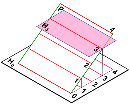
1、用一条等高线和平面的坡度表示平面,如图10-7。

The plane is represented by a contour line and the slope of the plane.
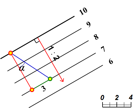
图10-7  平面的投影(1)

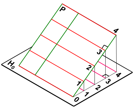
2、用平面上的一条倾斜线和平面的坡度表示平面,如图10-8。

A plane is indicated by an inclined line and the slope of the plane.

图10-8  平面的投影(2)

示坡线画法:方向平行于坡度线(即垂直于等高线),长短相间的细实线,短划为长划的1/3~1/2。如图10-9。

Slope line drawing method: the direction is parallel to the slope line (that is, perpendicular to the contour line), and the fine solid lines with long and short sections are 1/3 ~ 1/2 of the long section.
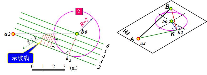
图10-9  示坡线的画法

3、用坡度比例尺表示平面,见图10-10。用坡度比例尺表示平面时,一定要画出标高投影的比例尺。

The plane is represented by a slope scale.When using the slope scale to represent a plane, be sure to draw the scale of the elevation projection.