
三视图的形成与投影规律 SECTION TWO FORM OF THREE VIEWS AND PROJECTION RULES
要获得投影,必须具备投射线、投影面、物体三个要素。画物体的正投影图,通常是用人的视线代替垂直投影面的投射线,运用线面的正投影性质在图纸上画出物体的正投影,因此正投影又称为视图。
To obtain the projection, the projection, must have three elements, object projection. Orthographic drawing objects, usually with the line of sight of people instead of vertical projection plane of projection, the projection properties, draw the projection of objects in the drawing, therefore is also called view projection
在工程上常用多面视图来表达物体,基本的表达方法是三视图。
Multi-views are often used to express solid in engineering field, meanwhile, three views are the basic representation.
一、三视图的形成 FORM OF THREE VIEWS
1.投影体系 PROJECTION SYSTEM
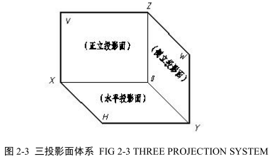
图 2-3 所示是按国标规定设立的三个相互垂直的投影面,称为三投影面体系。三投影面分别称为:正立投影面、水平投影面、侧立投影面,分别用 V、H、W 表示。两投影面之间的交线称为投影轴,相互垂直的三根轴分别用 OX、OY、OZ 表示。三根轴的交点 O 称为原点。
Projection system is called three- plane system for short. There are three mutually perpendicular planes. The vertical projection plane or V-plane is set up in front of observer.The horizontal projection or H-plane is set at right angle to the V-plane. The side vertical projection plane or W-plane is perpendicular to the H-plane and V-plane respectively. The intersection of the vertical and the horizontal planes give three lines which are axes of projection. The three intersection lines converge at a point which is the origin of projection.
为了作图方便,对物体长、宽、高三个方向的尺寸及上、下、左、右、前、后六个方位统一按下述方法确定:OX 轴方向为物体的长度方向,表示左、右方位;OY 轴方向为物体的宽度方向,表示前、后方位;OZ 轴方向为物体的高度方向,表示上、下方位。
In order to draw three views, some regulations are selected to express dimension and position of object. For example, the direction of OX axis determines the length of object and indicates left and right position. The direction of OY axis determines the height of object and indicates front and rear position. The direction of OZ axis determines the width of object and indicates top and bottom position of object.
2.分面进行投影 FORM OF VIEWS
如图 2-4(a)所示,把物体置于三面投影体系中,长、宽、高及上下、左右、前后方位即确定,然后将物体向三投影面进行投射得物体的三视图:
First, set an object into the projection system, then, the dimension and position of object have determined. Last, make orthographic projection of the object on the three projection planes individually.
从物体的前面向后投射,在 V 投影面上得到的视图叫主视图。
Front view: it is projected on the V- plane from front to rear of object. It represents length and height dimensions of object.
从物体的上面向下投射,在 H 投影面上得到的视图叫俯视图。
Top view: it is projected on the H- plane from top to bottom of object. It represents length and width dimensions of object.
从物体的左面向右投射,在 W 投影面上得到的视图叫左视图。
Left view: it is projected on the W- plane from left to right of object. It represents height and width dimensions of object.
3.投影面的展开 OPINING OF PROJECTION PLANES
要把三视图画在同一张图纸上,就需要把三个投影面展在一个平面中,方法如图2-4(b)所示:移去空间物体,V 投影面不动,将 H 投影面与 W 投影面沿 OY 轴分开,H投影面连同俯视图绕 OX 轴向下旋转 90°,W 投影面连同左视图绕 OZ 轴向右旋转 90°,即与 V 投影面成一平面,如图 2-4(c)所示。这时,OY 轴分为两个,随 H 投影面旋转的一个标为 YH ,随 W 投影面旋转的一个标为 YW 。展开后三视图的位置是:俯视图在主视图正下方,左视图在主视图正右方。
One wants to draw three views in the same plane of sheet and needs to open the three projection planes, as shown in fig2-4(b).it is assumed that the V-plane is stationary and the other two planes are hinged to it. Then revolve the H-plane downward and the W-plane to the right until they become in the same plane as the V-plane. Thus three views produce. In this case, the projection axis OY appears both to the right of the axis OX and below the axis OZ. The axis OY is labeled and along H the W- planes, respectively.
画物体的三视图时,必须遵守展开后的位置关系,并且不需要标注图名、不需要画投影面的边框线,初学时一般用细实线绘制出反应物体三视图之间关系的辅助线,如图2-4(d)所示。
To simplify the drawings, the boundaries of the three projection planes, the names of views are usually not shown. Beginners generally draw aided line to keep relationship between views with thin solid line as shown in Figure 2-4 (d).

三视图的画法 THREE VIEWS CONSTRUCTIONS
三视图的分析 ANALYSIS OF THREE VIEWS
1.三视图与空间物体间的关系 SPATIAL POSITION BETWEEN THREE VIEWS AND OBJECT
由三视图的形成可知,每个视图都表示物体两个方向的尺寸和四个方位,如图 2-5(a)所示。
According to the form of three views, every view can express two dimensions and four positions of object, as shown in fig2-5(a).
主视图反映物体长和高方向的尺寸和上下、左右方位;
The front view shows up and down , left and right relations of drawing features and it reflects the height and length of object.
俯视图反映物体长和宽方向的尺寸和左右、前后方位;
The top view shows front and rear , left and right relations of drawing features and it reflects the width and length of object.
左视图反映物体高和宽方向的尺寸和上下、前后方位。
The left view shows front and rear, up and down relations of drawing features and it reflects the height and width of object.
应当注意:俯视图和左视图远离主视图的一边是物体的前边,靠近主视图的一边是物体的后边。这一点一定要从三视图展开过程中彻底搞清楚。
One should keep in mind that the side far away from the front view is the front side; however, the side close to the front view is back side of object. So does the left view.
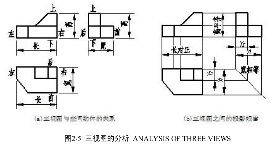
2.三视图间的投影规律 PROJECTION RULES OF THREE VIEWS
三视图表达的是同一物体,而且是物体在同一位置分别向三投影面所作的投影,所以,如图 2-5(b)所示三视图间必然具有以下所述的投影规律:
As we know , the three views reflect the same solid and ,meanwhile , the location of solid is stationary , so the three views obey the following projection rules.
主视图和俯视图长对正;
The length of the front view and top view should be aligned 英[əˈlaɪn]美[əˈlaɪn] and is equal.
主视图和左视图高平齐;
The height of the front view and left view should be aligned and is equal.
俯视图和左视图宽相等。
The width of the top view and left view should be aligned and is equal.
三视图间的投影规律,通常概括为:“长对正、高平齐、宽相等”九个字。这个规律是画图和读图的根本规律,无论是整个物体还是物体的局部,三视图间都必须符合这个规律。
Projection rules are often called length alignment, height alignment and width equality for short. One should apply the rules not only the whole solid, but also parts while drawing or reading figures.
应当注意:物体的宽度在俯视图中为竖直方向,在左视图中为水平方向,作图时,要注意宽度尺寸量取的方向和起点。
One should notice the direction of width in the top view is vertical, and in the left view is horizontal.one also needs to pay attention to the direction of width while being measured.
3.三视图绘制 CONSTRUCTION STEPS OF THREE VIEWS
Firstly, set the object in the three projection system and choose a proper position of relative to the projection system.
Secondly, make projection from three different view directions based on characteristics of orthographic projection and projection rules.
Lastly, check the three views with the rules and darken the drawings. The drawing steps are the following in details.
Step1 draw the datum line and layout the three views.
Step2 draw the feature view. Consider the position of solid and determine the projection. First draw true shape projection, then collecting projection, lastly, finish foreshortened projection.
Step3 draw the other two views based on the knowledge mentioned above.
Step4 check and correct, then darken the drawing. One should make it clear that the three views must follow the projection rules. One also needs to remember to draw dash line if the structure is invisible.
Examples: p2-1 exercise 2 and exercise 6.
Analysis of the question 2.
The object is made of two solids and its front view is the feature view. Follow the projection rule and draw top and left views.
Remember to draw aided lines to keep width equality between top and left views. The three views are as shown in fig exercise 2.
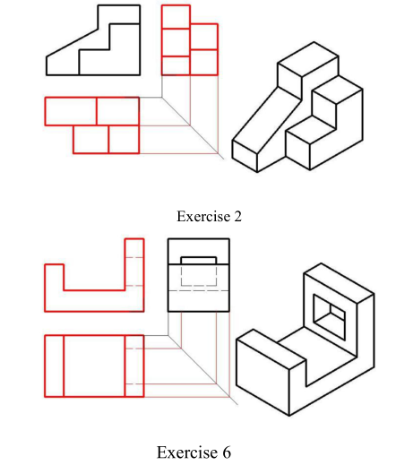
Analysis of the question 6.
Tips : remember to draw dash line If some outlines are invisible.

