水利工程制图

武心嘉

目录

  • 1 制图基本知识 Basic Knowledge of Drawing
    • 1.1 绪论 Introduction
    • 1.2 制图工具及其用法 Drawing Tools and Their Utilization
    • 1.3 国家标准有关规定 Related Provisions in National Standards
    • 1.4 几何作图geometric construction
    • 1.5 平面图形的绘制 The drawing of plane graphics
  • 2 投影的基础知识 The basics of projection
    • 2.1 投影法和投影特性 Projection method and projection properties
    • 2.2 工程中常用的四种投影图Four kinds of projection drawings commonly used in engineering
    • 2.3 物体的三面投影图 Three-sided projection of an object
  • 3 点线面的正投影 Projection of point、line and plane
    • 3.1 点的投影 Projection of Point
    • 3.2 直线的投影 Projection of Line
    • 3.3 平面的投影 Projection of Plane
    • 3.4 直线与平面、平面与平面的相对位置The position of a line relative to a plane, plane relative to a plane
  • 4 立体 Stereoscopic
    • 4.1 平面体的投影Projection ofProjection of  Planar Solids
    • 4.2 平面立体表面上的点和线 Points and lines on a planar solid surface
    • 4.3 平面立体截交线Plane stereo intersection line
    • 4.4 曲面立体的投影Stereoscopic projection of a curved surface
    • 4.5 曲面立体表面上的点和线Points and lines on the surface of a curved surface
    • 4.6 曲面立体的截交线Curved solid intersection
  • 5 立体表面相交Intersections of solids
    • 5.1 概述Overview
    • 5.2 两平面立体相交Two plane solids intersect
    • 5.3 平面体与曲面体相贯Intersections Between Planar and Curved Solids
    • 5.4 两曲面体的相贯线 The intersecting line of two curved bodies
    • 5.5 常见两曲面立体相贯线的讨论Discussion on the intersecting line of two surfaces
  • 6 组合体 composite solid
    • 6.1 组合体构成分析 Composition analysis
    • 6.2 组合体视图的画法 Composition View
    • 6.3 组合体的尺寸标注 The dimension of the assembly
    • 6.4 组合体视图的阅读 Reading the composite view
  • 7 轴测图的画法  construction of axonometric drawing
    • 7.1 轴测图的基本知识 Basic Knowledge
    • 7.2 平面体的正等测 Isometric Drawing
    • 7.3 平面体的斜二测 Cabinet Drawing
    • 7.4 曲面体的正等测 Isometric Drawing of Curved Solids
    • 7.5 曲面体的斜二测 Cabinet Drawing of Curved Solids
  • 8 工程形体的表达方法Expression methods of engineering objects
    • 8.1 视图 Views
    • 8.2 剖视图 Section View
    • 8.3 断面图 Cross Section
    • 8.4 简化画法和规定画法Simplified and prescriptive drawing
    • 8.5 视图的综合运用 Comprehensive use of views
    • 8.6 补充
  • 9 水工建筑物中常见的曲面 Curved surfaces in water conservancy project
    • 9.1 概述
    • 9.2 椭圆柱和椭圆锥
    • 9.3 双曲抛物面
    • 9.4 组合面Combination of surface
  • 10 标高投影 Projection with heights
    • 10.1 点、直线、平面 Points, lines, planes
    • 10.2 两平面的交线
    • 10.3 曲面和地形面 Curved and topographic surfaces
    • 10.4 标高投影在工程中的应用Application in engineering
  • 11 水利工程图 Hydraulic drawing
    • 11.1 水工建筑物和水工图 Hydraulic structures and drawings
    • 11.2 水利工程图表达 Expression of Hydraulic Engineering Drawing
    • 11.3 水工图的尺寸标注 Dimensioning of hydraulic drawings
    • 11.4 水工图的绘制 Drawing of hydraulic drawings
    • 11.5 水工图的阅读 Reading of hydraulic drawings
  • 12 水利工程制图实训
    • 12.1 题目
  • 13 建筑施工图Building construction drawing
    • 13.1 概述Overview
    • 13.2 建筑总平面图General plan of the building
    • 13.3 建筑平面图Construction plan
    • 13.4 建筑立面图 Elevation of Building
    • 13.5 建筑剖面图Building profile
    • 13.6 建筑详图 Architectural detailed drawing
建筑平面图Construction plan

建筑平面图Construction plan


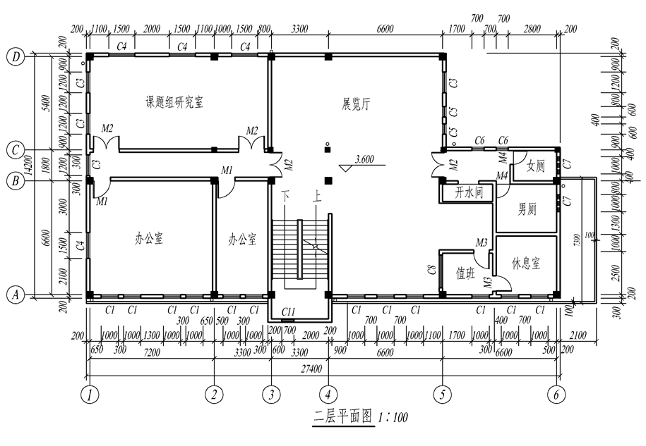
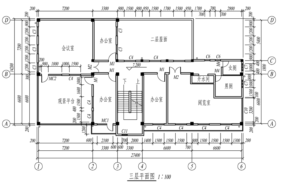
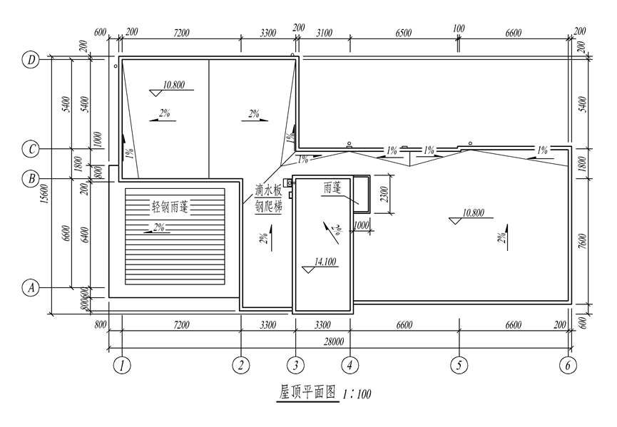
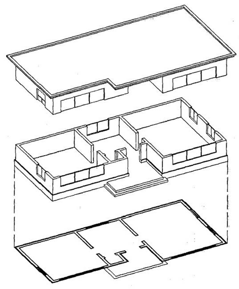
      建筑平面图主要表示房屋的平面形状、大小、房间布置、门窗位置、楼梯、走道布置、墙体厚度及承重构件的尺寸等。建筑平面图是施工放线、砌墙和安装门窗等的依据,是施工图中最基本的图样之一。

      Architectural plan mainly shows the plane shape of the house, size, room layout, location of doors and Windows, stairs, walkway layout, wall thickness and the size of load-bearing components. The architectural plan is the basis for laying out lines, laying walls, installing doors and Windows, etc. It is one of the most basic drawings in the construction drawing.

举例: